USB (“Universal Serial Bus”) is an interface for transferring data from external media to a computer, establishing connection and interchange between them. Today, most gadgets cannot do without it. USB has been available since 1996 and is currently considered standard.
There are currently four generations of USB specifications: USB 1.x, USB 2.0, USB 3.x and USB4.
USB is divided into 2 types: A and B. The first group includes active ones (connected to the “mother” and provides power), the other (connected to the “father”, these are connected devices) - passive.
In addition to types, USB is divided into “father” (Male) and “mother” (Female).
USB pinout on the motherboard: what, where and how
Most modern peripheral devices are connected via a universal serial bus. Therefore, the USB pinout on the motherboard plays a very important role in the operation of a modern computer. There are two ways to install these connectors. The first is mounting directly on the board. At the same time, it is displayed on the back side and is immediately ready for use. But it’s not always convenient to connect to it, so we developed another method. Its essence lies in a prepared footprint on the main PC board, to which wires from the front panel are connected. And the connector is located on it.
One USB 2.0 universal serial port has 4 pins. The first of them is designated “+5V”. It provides power to the peripheral device. The second and third are contacts through which information is transmitted. They are designated “DATA-” (minus data transfer) and “DATA+” (plus data transfer), respectively. The last one, the 4th one, which includes the USB pinout on the motherboard, is “GND” - ground supply. In accordance with today's standards, they are designated by the following colors: power - red, "DATA-" - white, "DATA+" - green, and "GND" - black.
Such interface connections are made in pairs, so the board has 2 USB standard connectors on one contact group. The wiring consists of 9 contacts: 4 to one connector, 4 to another, and the last two play the role of a so-called key. There is a pin installed in one place, but not in another. This is done so that it is impossible to confuse them and to make the connection correctly. The fitting from the front panel is made in a similar way. Therefore, when connecting, the first to the second should be installed without problems. If this does not happen, then you need to see if you are doing everything correctly.
Recently, version 3 of the USB standard has become increasingly popular. The pinout on the motherboard is significantly different, since significantly more wires are used to transmit information. There are only 9 of them in this design. In addition to the previously mentioned 4, 2 pairs of “Superspeed” + and 2 pairs of the same type, but only with a minus, are added, as well as “GND Drain” - additional ground. It is the larger number of wires that allows you to increase the data transfer speed. Their wires are designated blue by color, purple for minus, yellow, orange for plus, and another black for additional grounding. As the number of wires increases, the USB pinout on the motherboard increases in direct proportion. For this standard, 19 contacts are already used. One of them is a key, and its purpose is to ensure that the connection is correct.
Using the universal serial bus, a great variety of devices are connected to modern computers and laptops. A printer, scanner, MFP, flash drives, keyboard, mouse and other devices that significantly expand the capabilities of a PC - all of this is connected to the computer via this interface. It is not always convenient to connect to the back of the computer, and the number of integrated connectors may not be enough. It is to solve this problem that the USB pinout was made on the motherboard, which allows you to significantly increase the number of ports.
Connecting additional USB ports on your computer
USB is one of the most popular interfaces, used in the vast majority of devices. Almost any equipment is connected through it - from a regular mouse to a smartphone or gamepad. The problem is that sometimes there are so many devices that there are not enough connectors to connect them.
If nothing can be done with the laptop (the only option is to purchase a special adapter), then there is always the opportunity to install a couple of additional ports in the computer system unit. Let's see how to connect USB to a computer.
Connecting the front ports
Almost all modern system units are equipped with several USB connectors, which are located not on the back, but on the front panel. However, they usually do not work because they are not connected to the mother card.
Attention! All work is carried out with the computer turned off from the network.
Turn off the computer and remove the side cover. Locate the wires that come from the front of the system unit. They can be a coiled bundle of several thin cables or a solid wire.
Look carefully at the motherboard - there should be a connector on it, next to which it says USB (usually it is blue). Install the wire from the front ports into the motherboard connector. Assemble the system unit and turn on the computer. Now the front ports should work: you can, for example, connect Lenovo to a computer using them.
Installation of additional equipment
Do you want to connect a gamepad to your computer, but all the connectors, including the front ones, are occupied by other devices? Then you will have to purchase a USB controller that is installed in the PCI slot on the motherboard. If you connected a video card, you can easily install another card if there is a free slot.
If there are no free slots left on the motherboard, use external USB hubs.
Such devices are connected to an existing connector and allow you to seriously increase the number of ports. By installing several controllers and adding a number of hubs, you can increase the number of working USB ports to 127 (this is a protocol limitation; it simply won’t work anymore). Of course, the average user is unlikely to need such a number, but a couple of ports will never be superfluous.
How to enable data transfer mode on Android?
If for some reason the USB data transfer mode is not enabled, you can do this through the “For Developers” mode. There is no need to worry, we don’t need to hack or install anything, and the mode itself is very easy to enable in all Android systems by default.
- So, first we need to enable this mode. To be honest, this is not even a mode, but just an item in the settings menu. Go to “Settings” and find the “About phone” item - it can be located right here or in the “System” section. When you get inside, tap on the inscription: “Build number” several times. You will see messages like “You are getting close!” begin to appear on the screen. Then you will have to enter your PIN code - the inscription “You are now a developer” will appear at the bottom.
- Now go to the “System” section. A new item will appear there - “For Developers”.
- Scroll to “Default USB Configuration” and enable “File Transfer” mode.
NOTE! If you use USB modem mode in the future, you will need to immediately switch this mode manually.
After this, we pull out the wire and reconnect it to check the connection. If your smartphone refuses to connect, or some data is not displayed in Windows, try turning on USB Debugging. If this doesn't help, look at the next chapter.
USB 2.0 connector pinout (types A and B)
Since the physical plugs and sockets of early versions 1.1 and 2.0 do not differ from each other, we will present the wiring of the latter.
Figure 6. Wiring the plug and socket of type A connector
Designation:
- A – nest.
- B – plug.
- 1 – power supply +5.0 V.
- 2 and 3 signal wires.
- 4 – mass.
In the figure, the coloring of the contacts is shown according to the colors of the wire, and corresponds to the accepted specification.
Now let's look at the wiring of the classic socket B.
Wiring of plug and socket type B
Designation:
- A – plug connected to the socket on peripheral devices.
- B – socket on a peripheral device.
- 1 – power contact (+5 V).
- 2 and 3 – signal contacts.
- 4 – ground wire contact.
The colors of the contacts correspond to the accepted colors of the wires in the cord.
USB ports not working due to controller damage
If none of the above actions helped restore the functionality of the USB ports, then you should check the USB controller of the motherboard, which may have failed. In this case, high-quality repairs and diagnostics should be entrusted to the specialists of the service center. As a way out of the problem, try installing an expansion card, the so-called USB PC controller, which is installed in the PCI slot on the motherboard. This solution is noticeably cheaper than repairing the motherboard USB controller, and when using an additional USB hub, the problem with the lack of ports will not be relevant at all.
USB device and purpose
Rj-45: pinout, diagrams, standards and description of the standard
The first ports of this type appeared in the nineties of the last century. After some time, these connectors were updated to the USB 2.0 model. The speed of their work has increased more than 40 times. Currently, computers have a new USB 3.0 interface with speeds 10 times faster than the previous version. There are other types of connectors of this type, known as micro and mini USB, used in modern phones, smartphones, and tablets. Each bus has its own wiring or pinout. It may be required if you need to make your own adapter from one type of connector to another. Knowing all the intricacies of the arrangement of wires, you can even make a charger for a mobile phone. However, please remember that if connected incorrectly, the device may be damaged.
The USB 2.0 connector is designed as a flat connector with four pins. Depending on the purpose, it is labeled as AF (BF) and AM (BM), which corresponds to the common name “mother” and “father”. Mini and micro devices have the same markings. They differ from conventional buses in that they have five contacts. A USB 3.0 device looks similar to the 2.0 model, except for the internal design, which already has nine pins.
Ways to run msconfig
Second method (Windows XP, Vista, 7, 8, 10)
Go to the Start menu - All Programs - Accessories. Select “Command Prompt”. A black command line window will appear, type in it and press Enter.
Third method (Windows XP, Vista, 7, 8, 10)
In the same Start menu, click “Run”. A window will appear asking you to enter the required command. Here we enter , and press Enter as usual.
Fourth method (Windows XP, Vista, 7, 8, 10)
Go to Explorer at C:\Windows\System32. There are a lot of files in this huge folder. Scroll to the middle of the list and find msconfig.exe.
It makes no difference which of the proposed methods you use. The first one is the most optimal, as it is the fastest.
Connect the USB connectors on the front panel of the case to the motherboard
Hello friends! The USB interface has become firmly entrenched in the life of any computer user. Thanks to its versatility and ease of use, you can use it to connect a lot of devices - a table lamp, a fan, a gamepad, a gaming wheel, a flash drive, an external hard drive and much more.
Frequent use of ports located on the rear side is not always convenient, as access to them can be difficult. Currently, most cases are equipped with USB ports on the front panel, the number of which may vary depending on the model.
Processor connection
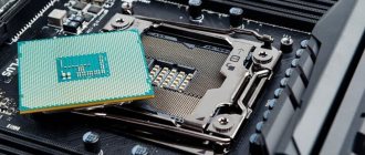
The processor is the “heart” of the computer, without which it simply will not work. For the processor, there is a notch in the center of each motherboard called a socket.
Depending on the manufacturer of the processors for which they are intended, sockets come in two types:
- AMD. This variety has many small holes with contacts into which the “feet” located on the processor are immersed.
AMD processor
- Intel. Here everything is the other way around: the legs are located on the socket itself, and there are flat copper contacts on the processor.
Intel processor
To connect the processor, you need to carefully place it in the socket and close the latch. In this case, you need to be very careful, as you can bend or break one of the legs
There is nothing wrong with a bent leg; it can be carefully straightened with tweezers. But if the contact is broken, you will have to take the processor to a service center
Here is a video tutorial on connecting the processor:
USB 3.0 pinout types A and B
Bus version 3.0 has a 10 or 9 wire connection. 9 pins are used if Shield wire is missing. The contacts are arranged in such a way that devices of earlier modifications can be connected.
USB 3.0 wiring:
- A – plug;
- B – socket;
- 1, 2, 3, 4 – contacts that match the pinout of the contacts in specification 2.0, have the same color scheme;
- 5, 6 contacts for data transmission via the SUPER_SPEED protocol are designated SS_TX- and SS_TX+, respectively;
- 7 – grounding GND;
- 8, 9 – contact pads of wires for receiving data via the SUPER_SPEED protocol, contact designation: SS_RX- and SS_RX+.
USB 3.0 pinout (types A and B)
In the third generation, peripheral devices are connected via 10 (9 if there is no shielding braid) wires; accordingly, the number of contacts is also increased. But they are located in such a way that it is possible to connect devices of earlier generations. That is, the +5.0 V contacts, GND, D+ and D-, are located in the same way as in the previous version. The wiring for Type A socket is shown in the figure below.
Figure 8. Pinout of Type A connector in USB 3.0
Designation:
- A – plug.
- B – nest.
- 1, 2, 3, 4 – connectors fully correspond to the pinout of the plug for version 2.0 (see B in Fig. 6), the colors of the wires also match.
- 5 (SS_TX-) and 6 (SS_TX+) connectors for data transmission wires via the SUPER_SPEED protocol.
- 7 – ground (GND) for signal wires.
- 8 (SS_RX-) and 9 (SS_RX+) connectors for data receiving wires using the SUPER_SPEED protocol.
The colors in the figure correspond to those generally accepted for this standard.
As mentioned above, a plug from an earlier model can be inserted into the socket of this port; accordingly, the throughput will decrease. As for the plug of the third generation of the universal bus, it is impossible to insert it into the sockets of the early release.
Now let's look at the pinout for the type B socket. Unlike the previous type, such a socket is incompatible with any plug of earlier versions.
Wiring USB 3.0 type B
Designations:
A and B are plug and socket, respectively.
Digital signatures for contacts correspond to the description in Figure 8.
The color is as close as possible to the color markings of the wires in the cord.
Pinout of USB 2.0 connector types A and B
Classic connectors contain 4 types of contacts, while mini and micro formats contain 5 contacts. Wire colors in USB 2.0 cable:
- +5V (red VBUS), voltage 5 V, maximum current 0.5 A, intended for power supply;
- D- (white) Data-;
- D+ (green) Data+;
- GND (black), voltage 0V, used for grounding.
For mini format: mini-USB and micro-USB:
- Red VBUS (+), voltage 5 V, current 0.5 A.
- White (-), D-.
- Green (+), D+.
- ID - for type A it is closed to GND to support the OTG function, but for type B it is not used.
- Black GND, voltage 0V, used for grounding.
Most cables have a Shield wire; it has no insulation and is used as a shield. It is not marked and is not assigned a number. The universal bus has 2 types of connectors. They are designated M (male) and F (female). Connector M (male) is called a plug, it is inserted, connector F (female) is called a socket, it is inserted into it.
Pinout features
When talking about the pinout of a USB connector, you need to understand the symbols indicated on the diagrams. It’s worth starting with the type of connector - active (type A) or passive (type B). Using an active connector, information can be exchanged in two directions, and a passive connector only allows it to be received. You should also distinguish between two forms of connector:
- F - "mother".
- M - "dad".
USB connector
With compatibility between 3.0 and 2.0, everything is somewhat more complicated. A device or cable of the second version can be connected to the new connector, and backward compatibility exists only for active type A connectors. It should be noted that the USB interface allows you to supply a voltage of 5 V to the connected gadget with a current of no more than 0.5 A. For the USB standard 2.0, the color layout from left to right is as follows:
- Red - positive contact of constant voltage of 5 V.
- White - data-.
- Green - data+.
- Black is the common wire or ground.
The connector circuit is quite simple, and if necessary, repairing it will not be difficult. Since version 3.0 has increased the number of contacts, its pinout also differs from the previous standard. Thus, the color scheme of the contacts is as follows:
- Red - 5 V+.
- White - data-.
- Green - data+.
- Black is common.
- Purple - welcome.
- Orange - reception+.
- Without color - earth.
- Blue—transmission-.
- Yellow - transmission+.
Micro and mini connectors
Miniaturization of the connector had a negative impact on reliability. Although mini-USB has a large resource, after a fairly short period of time it begins to dangle, but does not fall out of the socket. Micro-USB is a modified version of mini-USB. Thanks to the improved fastening, it turned out to be more reliable. Since 2011, this connector has become a unified standard for charging all mobile devices.
USB 3.0 and other subtleties
However, this is true in cases where ports of the same generation are used.
If the motherboard has a second or third revision, and a similar situation is observed with the front panel, compliance is necessary: USB 3.0 should be connected only to the corresponding slot on the motherboard, otherwise it will operate at USB 2.0 speed.
There is no need to worry about the pinout: it is the same for both revisions. In addition, motherboard manufacturers - ASUS, MSI, Gigabyte, Asrock and smaller companies, follow the same pinout that case manufacturers follow.
However, keep in mind that in rare cases it may still differ from the generally accepted one. You can find out the necessary information in the documentation for the motherboard.
Do not worry that you can connect the USB port incorrectly - in this case it simply will not work. Fortunately, it is impossible to break your computer this way.
Before installing the device
Check the device documentation to see if you need to install a driver before connecting the device. Although Windows typically installs drivers automatically when new devices are connected, some devices require you to install drivers manually. In such cases, device manufacturers provide a software disc and instructions for installing the driver before connecting the device.
If the USB device came with manufacturer's software, check to see if it is compatible with your current version of Windows. If it's not compatible or you don't know what version of Windows it's for, try connecting the device first to see if Windows can find a compatible driver.
Follow the instructions in your device documentation, even if they conflict with the information in this section.
How to properly connect the front panel to the motherboard
Often, a person who is assembling a computer for the first time (and it happens that it is not the first time) is faced with the fact that he does not know how to correctly and where to connect reset buttons, power buttons, LED indicators, a speaker that makes a squeak when turned on . I will show several examples by which you can understand the principle of how any front panel is connected correctly, and I will tell you some secrets that I use in my work.
There is nothing complicated about this if you adhere to simple rules and recommendations, which will be discussed now.
Where to connect the connectors?
This section is for those who do not know where exactly the front panel is connected. If this doesn't apply to you, skip straight to the next section and read on.
First, let's figure out what the place on the motherboard where the front panel of the computer is connected generally looks like. For clarity, I just want to show a few photos, from them you can easily determine what this connector looks like on the motherboard:
As you can see, they may differ slightly from each other
I also want to draw your attention to the fact that the location at the bottom right is not mandatory; sometimes these contacts are located in the center at the bottom of the motherboard
How to properly connect the front panel connectors?
Most motherboards already have markings on what to connect and where. Here is the simplest and most obvious example:
From left to right in the photo:
+MSG- (yellow) – connection of the computer operation indicator;
+HD- (blue color) – connection of the hard disk drive (HDD) operation indicator;
+PW- (red color) – connection of the power button;
-RES+ (green color) – connection of the reset button;
+SPEAK- (orange color) – connecting a speaker (the one that makes a squeak when turned on);
The colors don’t mean anything here, the manufacturer just decided to make such markings.
Rules for connecting connectors:
There are simple general rules, using which you will correctly and easily connect the front panel connectors to the motherboard:
Connecting the Power and Reset buttons has no polarity, since these buttons simply work to close the contacts
Despite the fact that the board indicates + and – for these buttons, they have no meaning. It is important to observe the polarity when connecting the LEDs and the speaker, otherwise they will not work. On the motherboard, for each type of connector, its plus is always on the left, and its minus is on the right. This is true for all motherboards
Important information
First, examine the appearance of each available connector on the motherboard, as well as the cables for connecting front panel components
When connecting, it is important to follow a certain order, because if you connect one or another element in the wrong order, it may not work correctly, not work at all, or disrupt the operation of the entire system
Therefore, it is important to study the location of all elements in advance. It will be very good if there is an instruction or other paper for the motherboard that explains the order of connecting certain components to the board
Even if the documentation for the motherboard is in a language other than Russian, do not throw it away.
It is not difficult to remember the location and name of all elements, because... they have a certain appearance and are marked. It should be remembered that the instructions given in the article are general in nature, so the location of some components on your motherboard may be slightly different.
Stage 1: connecting buttons and indicators
This step is vital for the operation of the computer, so it must be completed first. Before starting work, it is recommended to disconnect the computer from the network to avoid a sudden power surge.
There is a special block on the motherboard, which is intended only for arranging the wires of indicators and buttons. It is called "Front panel", "PANEL" or "F-PANEL". On all motherboards it is signed and located at the bottom, closer to the intended location of the front panel.
Let's look at the connecting wires in more detail:
- Red wire – designed to connect the on/off button;
- Yellow wire – connects to the computer reset button;
- The blue cable is responsible for one of the system status indicators, which usually lights up when the PC reboots (some models of cases do not have this);
- The green cable is designed to connect the motherboard to the computer's power indicator.
- The white cable is needed to connect the power.
Sometimes the red and yellow wires “change” their functions, which can be confusing, so it is advisable to study the instructions before starting work.
The places for connecting each wire are usually marked with a corresponding color or have a special identifier, which is written either on the cable itself or in the instructions. If you don’t know where to connect this or that wire, then connect it “at random”, because... Then you can reconnect everything again.
To check that the cables are connected correctly, connect the computer to the network and try turning it on using the button on the case. If the computer turns on and all the indicators are on, it means you have connected everything correctly. If not, then disconnect the computer from the network again and try swapping the wires; perhaps you simply installed the cable on the wrong connector.
OTG - DIY adapter
Connector pinout of ethernet connector cable connection diagram
Not all old tablets support the function of connecting a flash drive or modem, but I will tell you how to outsmart them and connect a flash drive, modem, or even a hard drive to them. Good afternoon, homemade people!
Today I would like to present to your attention an OTG adapter.
First, I want to tell you what OTG is? This is a way to connect to your tablet or phone that supports the OTG function, printer, flash drive and even hard drive. This connection is also called USB-host.
You can also connect a keyboard or mouse to your gadget, if the gadget supports such a function.
And so, to create this miracle cable, we will need: • An old USB extension cord • Micro USB connector (you can get it from a regular USB cable for your device) • A soldering iron and soldering accessories
And so, let's go, to make such a cable, we will need to connect the 4th pin to the 5th pin of the micro USB connector
We must get to the fourth pin and connect it with a jumper to the GND wire as shown in the picture
After we connect the 4th and 5th contacts with a jumper, our gadget will perform the function of an active device and will understand that another passive device is about to be connected to it. Until we install a jumper, the gadget will continue to act as a passive device and will not see your flash drives.
But that’s not all; to connect a hard drive to a phone or tablet, this adapter will not be enough for us. To connect devices whose consumption is more than 100mA, namely 100mA can be supplied by the port of your device, we will need to connect additional power to our OTG cable, which should be enough for your hard drive to work.
Here is a diagram of such an adapter
Now it's time to start assembling. We take the old USB extension cable and cut it not too far from the 2.0 connector, since the current is only 100mA, to avoid large losses. Cut approximately in the same place as shown in the photo
Afterwards we clean our wire
Next, it needs to be tinned and soldered as shown in the diagram. You need to tin approximately 1mm of the wire, since the contacts on the micro USB connector are very small. This is what happened to me.
I connected pins 4 and 5 with a drop of solder.
Well, here is our entire cable assembled
All that remains is to check the functionality, take the tablet, insert the “adapter” and insert the flash drive into it, everything works, as the flashing LED on the flash drive and the tablet detecting the flash drive tell us.
Limitations: Old mobile phones cannot do this. The flash drive must be formatted in FAT32. The maximum capacity of the connected flash drive is limited by the hardware capabilities of the phone or tablet.
Criterias of choice
When choosing an adapter, you need to pay attention to the following factors:
First of all, it is necessary to take into account technical features. The main characteristics are output voltage and current. If the adapter is purchased to charge mobile devices, then the output current should be 1 A; if you plan to connect a tablet, then the output current should be 2.1 A
To get a universal adapter, it is better to buy it with an output current of 2.1 A. The next nuance that you should pay attention to is the cable fastening. It is necessary to make sure that the place where the cable is attached to the connector and the AP has a seal made of special protection
During operation, the wire in an unprotected connection will bend and may break. An important factor is the length of the cable. A short cable will be inconvenient to use. It is advisable to purchase a device with a cable length sufficient to charge the devices of rear passengers. The case should be durable and not creak if you press it hard. High-quality devices have built-in short circuit protection.
Naturally, it is better to choose splitters with several switches and USB slots. This will make it possible to connect several gadgets at the same time.
Price issue
The cost of USB adapters and splitters depends on the quality and manufacturer. Branded products are always more expensive. Among inexpensive models you can also buy high-quality products.
1. Universal adapter from FLY (price from 100 rub.)
2. Waterproof adapter (price from 230 rub.)
3. USB Splitter adapter (price from 250 RUR)
Types of USB connectors - main differences and features
There are three specifications (versions) of this type of connection that are partially compatible with each other:
- The very first version that has become widespread is v 1. It is an improved modification of the previous version (1.0), which practically did not leave the prototype phase due to serious errors in the data transfer protocol. This specification has the following characteristics:
- Dual-mode data transfer at high and low speed (12.0 and 1.50 Mbps, respectively).
- Possibility of connecting more than a hundred different devices (including hubs).
- The maximum cord length is 3.0 and 5.0 m for high and low transfer speeds, respectively.
- The rated bus voltage is 5.0 V, the permissible load current of the connected equipment is 0.5 A.
Today this standard is practically not used due to its low throughput.
- The dominant second specification today... This standard is fully compatible with the previous modification. A distinctive feature is the presence of a high-speed data exchange protocol (up to 480.0 Mbit per second).
A clear demonstration of the advantages of USB 2.0 over other interfaces (transfer speed 60 MB per second, which corresponds to 480 Mbit per second). Thanks to full hardware compatibility with the younger version, peripheral devices of this standard can be connected to the previous modification.
True, the throughput will decrease up to 35-40 times, and in some cases more. Since these versions are fully compatible, their cables and connectors are identical.
Please note that, despite the bandwidth specified in the specification, the actual data exchange speed in the second generation is somewhat lower (about 30-35 MB per second). This is due to the implementation of the protocol, which leads to delays between data packets. Since modern drives have a read speed four times higher than the throughput of the second modification, that is, it does not meet current requirements
Since modern drives have a read speed four times higher than the throughput of the second modification, that is, it does not meet current requirements.
- The 3rd generation universal bus was developed specifically to solve problems of insufficient bandwidth. According to the specification, this modification is capable of exchanging information at a speed of 5.0 Gbit per second, which is almost three times the reading speed of modern drives. Plugs and sockets of the latest modification are usually marked blue to facilitate identification of belonging to this specification.
USB 3.0 connectors have a characteristic blue color.
Another feature of the third generation is an increase in the rated current to 0.9 A, which allows you to power a number of devices and eliminate the need for separate power supplies for them.
As for compatibility with the previous version, it is partially implemented; this will be discussed in detail below.
Options to add a USB-C jack for laptop users
If your laptop doesn't have USB-C ports and you need to connect something to it, the easiest way to do it is to use a simple cable. USB-C to USB-A cables (with a standard rectangular connector) are available in male and female versions. In fact, if your new gadget only connects via USB-C, like most new Android phones, it's likely that a C-to-A cable was included in the box. You can buy this very inexpensively at any electronics store.
Standard USB-A to USB-C cable.
When using these cables for anything other than charging, be sure to connect them to a USB 3.0 port. Ports 3 (and later) are not the same as ports A and C: the number refers to the version of the Universal Serial Bus, and the letter refers specifically to the shape and digital pins in the connection. Ports 3.0 and higher offer significantly faster speeds than the old 2.0 standard. 3.0 ports are sometimes marked with blue connectors or other obvious color changes or a symbol like this:
Enabling ports in BIOS
To enter the BIOS during boot, press Delete, F2 or another key depending on the motherboard model. You can view it on the start screen.
In the case of a laptop, this screen does not appear because the fast boot feature is activated. You can temporarily disable this technology in the power settings:
Restart your computer. Without Quick Start, you will see all stages of Windows boot and can get into the BIOS. If this doesn't work on Windows 8 or 10 with UEFI BIOS, try the following method:
Once rebooted, select Diagnostics, then go to Advanced Options and open UEFI Firmware Options. Click "Reboot", the next time you start, the BIOS UEFI interface will appear.
To configure USB ports in UEFI, you need to go to the “Peripherals” tab and set the “Legacy USB Support” parameter to “Enabled”. If support for USB 3.0 ports is required, activate the corresponding item (USB 3.0 Support).
In the AMI BIOS, go to the “Integrated Peripherals” section and set the four options to “Enabled”:
- USB EHCI Controller.
- USB Mouse Support.
- USB Keyboard Support.
- Legacy USB Storage Detect.
In Phoenix AwardBIOS, you need to go to the “Advanced” tab and go to the “USB configuration” section. All parameters inside must be set to “Enabled” for the USB ports to work.
In all BIOS versions, to save the configuration, you must press the F10 key and confirm the selection by writing “Y”.
Main motherboard ports and their pinouts
The contacts present on motherboards can be divided into several groups: power connectors, connections for external cards, peripheral devices, and coolers, as well as front panel contacts. Let's look at them in order.
Nutrition
Electricity is supplied to the motherboard through a power supply, which is connected through a special connector. In modern types of motherboards there are two types: 20 pin and 24 pin. This is what they look like.
In some cases, four more are added to each of the main contacts to make the units compatible with different motherboards.
The first option is older; it can now be found on motherboards manufactured in the mid-2000s. The second one is relevant today and is used almost everywhere. The pinout of this connector looks like this.
By the way, by closing the PS-ON and COM contacts, you can check the functionality of the power supply.
PSU connectors
The power supply contains the main connectors (electrical connectors) previously used in old power supplies, supplying voltages of 3.3, 5 and 12 Volts. Each connector pin is one Pin.
Motherboard
connects to the power supply via a 24 Pin male connector (the so-called bus), which has undergone changes with the improvement of motherboards. Previous generations of motherboards were connected to the power supply via a 20 Pin bus.
Because of this, in order to support any type of connection to the motherboard, the connector is made in the form of a collapsible design with a 20 Pin main and 4 Pin additional power connector.
If the motherboard only needs 20 Pin, the 4 Pin connector is removed (pull down along the plastic rails) and bent to make it easy to install a 20-pin bus.
Molex 8981 connectors are used to power optical drives and other drives with a PATA (Parallel ATA) connection interface.
(by the name of the developer-manufacturer company).
SATA (Serial ATA) connection interface
for storage devices of all types.
Typically, to power storage devices
, the power supply has two special 15 Pin connectors (or there is an adapter for powering PATA HDD - SATA HDD).
Advice!
You can also connect a modern hard drive via molex, but connecting via SATA and molex at the same time is not recommended, since the HDD may not withstand the load and burn out.
Central processor
Requires power supply from a 4 or 8 Pin connector (can be detachable).
Video card
You need 6 or 8 Pin power. The connector can be dismountable to 6+2 Pin
Some modern power supplies may contain an outdated 4 Pin connector for floppy drives
, card readers, etc.
Also 3 and 4 Pin connectors are used to connect coolers
.
Connecting the front panel of the computer to the motherboard
If you decide to assemble or disassemble a computer, this article will be very relevant for you. It will discuss how to properly connect the panel of front buttons and USB ports on the system unit to the motherboard. Here, I will consider not only the general appearance of the ports to which they need to be connected, but also the correct order when connecting them.
In fact, there seems to be nothing complicated about this. But in my practice, even specialists who are fairly well versed in computer technology sometimes stand in front of a system unit with a bunch of cables and think about what needs to be connected and where.
Therefore, below I will show in detail what and in what connector this or that wire needs to be connected for the correct operation of the connected front panel of the system unit. That in the future, the next time you clean your computer or perhaps replace the motherboard, it will not be difficult for you to correctly connect all the elements of the system unit to the motherboard.
It is also very important if the front panel with USB ports and outputs for headphones and microphone does not work. Then, be sure to read it to the end to find out how to fix this whole thing and return our front USB ports to working condition. Because the problem may lie in the fact that they are simply not physically connected to the motherboard.
Connecting the front panel, button block and indicators
The block of buttons and light bulbs for turning on and rebooting is connected to the motherboard using four connectors, which are connected into one continuous cable. You can see what they look like for me below. They should have approximately the same appearance for you. The main thing is to look for those connectors that have similar phrases written on them: Power SW, Power LED, HDD LED. RESTART SW.
Let's look at each connector separately:
- POWER SW (PWRBTN) - is responsible for the computer power button;
- HDDLED (+HDLED) - a hard drive light that constantly blinks when the computer is running;
- POWER LED - and + (PLED) - indicator indicating the state of the computer (on or off);
- RESTART SW (RESET) - connector responsible for the reset button;
- SPEAKER - a tweeter speaker is sometimes also present in the cable panel;
Where should all this be connected? All connectors will connect to one port, which is located in the lower right corner of the motherboard. Manufacturers usually sign them with such designations as: “F_PANEL” or simply “PANEL”. On each motherboard, near such a panel, there are small signatures where what needs to be inserted. But still, below I will give you several examples of what to add to what.
Also, sometimes an additional small speaker is connected which notifies with a squeak that the computer is turned on, as well as about various BIOS and computer hardware errors. Sometimes it is connected with all the other connectors, but as a rule, a separate four-pion connector is allocated for it.
That's it, we're done with the button block, now we can move on to the front USB and audio outputs.
System unit front panel connections
The audio and USB connectors are very similar to those we connected for buttons and indicators. But their most important difference is that they are already immediately connected into one, and when connecting you do not need to take it and connect it one pin at a time.
You can also find the place for connection at the bottom of the motherboard with labels (F_USB1, 2). There may be two or more of them on the motherboard, but it doesn’t matter which one you connect to, they will work the same. The main thing you need to do is take the connector labeled “F_USB” and put it in the appropriate connector. You can’t make a mistake, because if you try to insert it the wrong way, you simply won’t succeed, and turning it over to the other side, I think everything should fall into place.
Be sure to pay attention if you have USB 3.0 on the front panel of your computer, then you will need to connect it to the appropriate connector. You can find out where it is located in the manual for your motherboard. Also, I want to draw your attention to the fact that if USB 3.0 is connected to a standard connector, it will work, just the transfer speed will be the same as on USB 2.0.
Connecting the front audio panel to the motherboard
The situation with sound is similar to USB. Here, too, the connectors are connected into one, which will allow you to easily and without errors connect it to the motherboard. The connector itself is usually located next to the USB ports and is designated by the following abbreviations; AAFP, AUDIO, A_AUDIO.
Taking a connector with the inscription “HD Audio” or “AC 97”, we connect it to the connector with one of the signatures, an example of which I indicated above. If after connecting the headphones and microphone still do not respond, then you should check the settings of the front audio panel in the BIOS. Sometimes it happens that the system uses the “AC97” driver, but the BIOS indicates “HD Audio”, which, due to mismatch, renders our audio outputs inoperative.
Checking BIOS settings
The first thing you should pay attention to is the computer's BIOS settings. To enter the BIOS you will need a working keyboard. If the keyboard is connected to the computer via USB and it does not work, then you need to connect a keyboard with a PS/2 connector. Otherwise, you simply won't be able to do anything.
So, let's go to the BIOS, for which, when starting the computer, you need to press the enter key, usually DEL. There may be another key that appears on the screen and is listed in the motherboard manual. After entering the BIOS, find the section responsible for integrated devices (Integrated Peripherals) or the “Advanced” section. Here you should find the “Onboard Devices Configuration” subsection. It contains the parameters responsible for the operation of USB controllers: USB Function or USB 2.0 Controller. These parameters must be Enabled. And if one of them is disabled, then hover over it and press Enter, thereby turning it on. To ensure that the changes you make are not lost, you must save them by pressing F10 and confirm saving by pressing the Y or Enter key.
After restarting the computer, check if the USB ports are working. And if not, then you should look for the reason elsewhere.
USB cable wiring by color
Since there are many specifications, and the type of connector imposes its own restrictions on the placement of contacts, the pinout differs from version to version. Therefore, they must be disassembled separately.
USB 2.0 pinout
The “classic” USB 2.0 connectors have 4 pins, while the mini and micro versions have 5. In any case, data is transferred via two of them. They are usually marked on diagrams as D- and D+. They correspond to the green and white colors of the cables. Standard A and B may have gold that actually looks just yellow. Two contacts are responsible for power. A voltage of 5 V is carried out one at a time. The colors of the cables are red and orange.
Sources
- https://math-nttt.ru/novosti/kak-pravilno-podklyuchit-usb-k-materinskoj-plate.html
- https://HouseChief.ru/raspinovka-usb.html
- https://besporovod.ru/raspinovka-usb-na-materinskoj-plate-chto-gde-i-kak
- https://crast.ru/instrumenty/raspinovka-usb-na-materinskoj-plate-po-cvetam
- https://sk-impuls.ru/raspinovka-usb-na-materinskoj-plate/
- https://svetluxe.ru/raspinovka-usb-na-materinskoj-plate/
- https://tv-st.ru/ustrojstva/razem-usb-na-materinskoj-plate.html
- https://BurForum.ru/elektrika-drugoe/vhod-yusb.html
- https://odinelectric.ru/wiring/wires/shema-raspinovki-usb-kabelya-po-tsvetam
- https://my-class.ru/kak-podklyuchit-usb-k-materinskoy-plate-4-vyvoda/
- https://exsofter.ru/raspinovka-usb-na-materinskoj-plate/
- https://veranda71.ru/raspinovka-usb-na-materinskoj-plate/
- https://GeshTV.ru/devajsy/podklyuchenie-yusb-k-materinskoj-plate.html
- https://LesSale.ru/glavnoe/podklyuchenie-provodov-usb-k-materinskoj-plate.html
- https://sib-bastion.ru/novoe/yusb-na-materinskoj-plate.html
