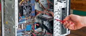
Most inexperienced computer users believe that connecting the front panel of the computer case, on which the power and restart buttons of the computer are located, as well as USB inputs and audio outputs, to the motherboard is a complex and difficult task.
But, as often happens, after spending 5 minutes studying the issue, everything becomes clear and very doable. In this article we will look at the sequence of actions that must be performed to successfully and correctly connect the front panel to the motherboard, be it a board from Asus, Gigabyte, Asrock, MSI and others.
How to connect wires to the motherboard - step-by-step instructions
To start connecting wires to the motherboard, the user needs to follow these steps:
- Install all elements of the system unit in place and securely fix them;
- Lay out all the wires separately from each other so as not to confuse anything during the assembly process;
- Stock up on zip ties or electrical tape. They are needed to fix the wires in a certain position after connection. This will free up a lot of free space, and the system unit will look neat and aesthetically pleasing;
Having completed these steps, you can proceed directly to connecting the MP. This is done as follows:
- The first step is to connect the connectors;
- Next, connect power to the processor;
- Connect the motherboard to power;
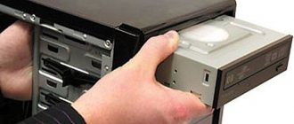
- The next thing you need to connect is the hard drive;
- Install the video card;
- Installing RAM;
Connecting wires to motherboards from Asus, Asrock, MIS and other manufacturers.
Every motherboard manufacturer uses standard layout methods. This means that the general algorithm for connecting the MP to other elements of the system unit is the same and differences can arise only in minor details. The description presented below will be suitable for any MP model, as it includes basic steps that are typical for all devices.
Back panel
If you look at the motherboard from above, on the left side you can see a set of soldered interfaces for connecting peripherals and I/O devices. When installing the MP, these sockets are located on the rear wall of the case. The set includes the following connectors:
- PS/2 – keyboard and mouse;
- USB0 – printers, scanners, mouse, keyboard, webcams;
- VGA/DVI/HDMI – monitor (if there is a built-in video core on the processor or the northern location of the MP);
- BIOS update and flash buttons (top versions);
- Wi-Fi antennas;
- Ethernet RJ-45 socket for connecting a network cable;
- audio connectors (including S/PDIF);
- COM port – for RS-232 cable (old peripherals, or for flashing TV tuners).
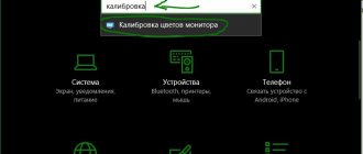
Connecting connectors
Connecting connectors allows you to connect the MP to the front panel of the system unit. This must be done first and will not take much of your time. Most manufacturers mark their connectors on the MP and the wires leading to the front panel with the same marking. Below is a breakdown of the symbols:
- Power SW – allows you to turn your PC on and off;
- Reset SW – is responsible for rebooting the system if necessary;
- Power LED - connected to special light bulbs that light up when the system starts, indicating a particular action. When connecting, do not confuse “+” and “-” in places;
- DDLED – recharge of the indicator responsible for indicating the loading of the hard drive;
- Connectors for USB and audio devices also have their own markings and you just need to connect the connector to the desired location on the MP;
Note! Some manufacturers do not directly mark their connectors, and to decipher their purpose you will need to look at the instructions included with the MP.
Main motherboard ports and their pinouts
The contacts present on motherboards can be divided into several groups: power connectors, connections for external cards, peripheral devices, and coolers, as well as front panel contacts. Let's look at them in order.
Nutrition
Electricity is supplied to the motherboard through a power supply, which is connected through a special connector. In modern types of motherboards there are two types: 20 pin and 24 pin. This is what they look like.
In some cases, four more are added to each of the main contacts to make the units compatible with different motherboards.
The first option is older; it can now be found on motherboards manufactured in the mid-2000s. The second one is relevant today and is used almost everywhere. The pinout of this connector looks like this.
By the way, by closing the PS-ON and COM contacts, you can check the functionality of the power supply.
Peripherals and external devices
Connectors for peripherals and external devices include contacts for the hard drive, ports for external cards (video, audio and network), inputs of LPT and COM types, as well as USB and PS/2.
Hard drive The main hard drive connector used today is SATA (Serial ATA), but most motherboards also have an IDE port. The main difference between these contacts is speed: the first is noticeably faster, but the second benefits due to compatibility. The connectors are easy to distinguish by their appearance - they look like this.
The pinout of each of these ports is naturally different. This is what the IDE pinout looks like.
In addition to these options, in some cases a SCSI input can be used to connect peripherals, but this is very rare on home computers. In addition, most modern optical and magnetic disk drives also use these types of connectors. We'll talk about how to connect them correctly another time.
External cards Today, the main connector for connecting external cards is PCI-E. This port is suitable for sound cards, GPUs, network cards, as well as diagnostic POST cards. The pinout of this connector looks like this.
Peripheral slots The oldest ports for externally connected devices are LPT and COM (otherwise known as serial and parallel ports). Both types are considered obsolete, but are still used, for example, to connect old equipment, which is not possible to replace with a modern analogue. The pinout of these connectors looks like this.
Keyboards and mice are connected to PS/2 type ports. This standard is also considered obsolete and is being replaced en masse by the more current USB, but PS/2 provides more opportunities for connecting control devices without the participation of the operating system, which is why it is still in use. The pin diagram for this port looks like this.
Please note that the inputs for the keyboard and mouse are strictly separated!
Another type of connector is FireWire, also known as IEEE 1394. This type of contact is a kind of forerunner of the Universal Series Bus and is used to connect some specific multimedia devices such as video cameras or DVD players. It is rarely found on modern motherboards, but just in case we will show you its pinout.
Attention! Despite their external similarity, USB and FireWire ports are incompatible!
USB today is the most convenient and popular connector for connecting peripheral devices, from flash drives to external digital-to-analog converters. As a rule, there are from 2 to 4 ports of this type on the motherboard, with the possibility of increasing their number by connecting the front panel (more about it below). The dominant type of USB now is type A 2.0, but manufacturers are gradually switching to standard 3.0, the contact pattern of which differs from the previous version.
Front panel There are special contacts for connecting the front panel: output of some ports (for example, line output or 3.5 mini-jack) to the front part of the system unit. The connection procedure and pinout of contacts have already been discussed on our website.
Conclusion
We have looked at the pinout of the most important contacts on the motherboard. To summarize, we note that the information presented in the article is sufficient for the average user.
Thank the author and share the article on social networks.
Processor power connection
Power to the processor and the cooler responsible for cooling is supplied through the MP, and not directly. The connector is a socket consisting of 4 pins. It is located in close proximity to the processor and is difficult to confuse with something else. If you still have problems, check the instructions that come with the MP. The power cable also has 4 wires arranged according to the connector.
Where is the best place to buy a motherboard?
If you are too lazy to wait for new articles on motherboards and have decided to run out and buy, then first of all we recommend three stores with approximately the same degree of quality:
- GearBest is for those who are not afraid to buy abroad and save money. There are many interesting SSDs of the “Chinese” type, several popular brands, and in general a pleasant store where there are constant promotions and so on;
- JUST is perhaps the best choice in terms of price-quality ratio of SSDs (and not only). The prices are quite reasonable, although the range is not always ideal in terms of variety. The key advantage is the guarantee, which really allows you to change the product within 14 days without any questions, and in case of warranty problems, the store will take your side and help solve any problems. The author of the site has been using it for at least 10 years (since the time when they were part of Ultra Electoronics), which he advises you to do;
- OLDI is one of the oldest stores on the market; the company has been around for about 20 years. Decent selection, average prices and one of the most convenient sites. Overall a pleasure to work with.
The choice, traditionally, is yours. Of course, no one has canceled all sorts of Yandex.Markets, but of the good stores I would recommend these, and not some MVideo and other large networks (which are often not only expensive, but defective in terms of quality of service, warranty work etc.).
Connecting a video card
There are 2 variations of video cards:
- With a 4 pin connector, which most standard models have;
- With 6 pin connector. Only powerful video cards of the latest models can boast of this;
In most cases, the power connector is located behind the video card. There are models in which the power connector is located on the side of the device. If your video card is integrated into the MP, you do not need to worry about powering it, however, such devices are low-power and most users prefer to purchase separate cards that require additional power.
Data Storage
To connect HDDs and SSD drives, a SATA interface (SATA 3.0) with a bandwidth of up to 6 GB/sec is often used. It replaced the old and terribly inconvenient IDE.
Also found in nature are lesser-known but popular connectors:
- M.2 is a modern standard for ultra-high-speed SSDs;
- eSATA is an interface that supports connecting hot-swappable drives.
- IDE is an obsolete serial port with low bandwidth. SATA has long been and unconditionally supplanted.
Connecting RAM
Connecting RAM does not require the use of wires, since memory cards are installed in special slots located on the MP. Connecting them is easy and you won't be able to install the board incorrectly. The sockets have special latches that securely fix the boards in place.
Important! When connecting wires to the motherboard, do it carefully and carefully, do not put too much pressure on the connectors. If the cable does not fit into its proper place, make sure that you are doing everything correctly.
You can also look at articles on the topics How to connect the power button to the motherboard and Connecting the motherboard to the power supply.
Socket
Central connector for connecting the processor. In fact, you select any motherboard in advance for a certain model of stone, and then you dance from there. There are currently 4 popular CPU sockets:
- Socket 1151v2, 2066 (Intel);
- Socket AM4, TR4 (AMD).
Yes, there are older sockets, but we keep up with the times and choose the latest hardware for modern platforms.