Purpose of BIOS
With its help, the initial boot of the computer is ensured.
First, controllers and connected devices are initialized. If a failure occurs, a corresponding message is displayed on the screen. Otherwise, the OS search begins on the following devices:
- hdd or ssd hard drive;
- USB flash drive;
- CD-ROM;
Sometimes the search takes place on the network using PXE technology.
Old computers did not have the same operating system that we are used to. Therefore, some functions were available from the BIOS. These are mostly simple tasks: playing CDs, DVDs, using simple browsers. Modern operating systems do not use advanced functions, but only their drivers. Today, the BIOS is only used at boot time or in emergency mode.
New updates can be downloaded from the manufacturers' official websites. However, there is no need to upgrade as long as the computer is working properly. The reason for changing the firmware may be significant changes in some parameters or expansion of functionality.
PC Health Check v2.3 – checking your PC’s readiness for Windows 11
On June 24, Microsoft officially announced Windows 11 as the successor to Windows 10, and this new operating system offers huge improvements for everyone.
Windows 11 is technically Windows 10 with a visual update and general improvements, but it requires new hardware features for security reasons. Earlier this week, Microsoft published a new PC Health Check tool to help users prepare their devices for the new OS. According to user reports and our own tests, the Windows 11 PC Health Checker doesn't work properly and simply returns the error message "Windows 11 can't run on this PC" without any proper explanation.
The bug was also seen on high-end PCs, and the PC health checker was not telling users why their PCs weren't meeting Windows 11 requirements.
Now, PC Health Checker has been updated and it can tell you the reason why your device is not supported for Windows 11. PC Health Checker version 2.3 comes with new pop-ups that help users identify the root cause of compatibility issues and their workarounds.
“We just updated the PC Health Check app. It now provides more detailed information about outstanding requirements,” Microsoft said.
According to the updated tool, devices with the following issues cannot upgrade to Windows 11:
- TPM 2.0 is a requirement to run Windows 11. We recommend that you check if TPM 2.0 is enabled.
- The system disk must be 64 GB or larger. Although this PC does not meet the system requirements to run Windows 11, you will continue to receive Windows 10 updates.
- This processor is not supported.
- The PC must support Secure Boot.
This new update for PC Health Check Tool will help users who suspected that Windows compatibility issues were related to TPM.
For those who don't know, the basic requirements for the new operating system include "TPM 2.0", a processor clocked at 1 GHz or higher, 2+ cores, 4 GB RAM, system firmware with UEFI and Secure Boot support, DirectX 12 compatibility and your device must have a minimum of a 9-inch HD (720p) display.
Even if you don't meet the above requirements, you can still run the new operating system on devices with Intel, AMD, and Qualcomm processors.
To update the PC Health Checker, you need to download the new version and run the .msi installer, which will automatically replace the old version.
Keep in mind that the new operating system is still in preview, and Microsoft plans to release the update to consumers later this year.
Types of BIOS
Equipment configuration occurs through the on-screen menu, for which the keyboard is used. The mouse does not work because the drivers have not yet been loaded to control it. If problems arise, it is possible to reset the settings.
Main manufacturers:
- American Megatrends;
- Phoenix Technologies (Award).
- Microid Research.
Award was a separate company until 1998, which was later bought by Phoenix. The color of the Bios Phoenix window, depending on the version, is blue or gray, the menu is only in English. The main window consists of two horizontal sections, under which there are hints about the assignment of keys. When navigating through the tabs, the main part of the window displays the menu items, with an explanation on the right.
Bios Phoenix has a simple graphical interface, similar to the classic one, which makes it easy to configure your computer.
PC health monitoring systems (Hardware monitor / PC Health)
1.ITE8712/05F
Both chips are very common today and are widely used in products from such famous manufacturers as Elite Group, PC Chips, Gigabyte, ASUS, Chaintech, Soltek. To measure voltages, 8-bit ADCs with a resolution of 0.016V and a range from 0 to 4.096V are used. To measure voltages greater than 4.096 V, resistive dividers are used, which reduces the measurement accuracy. Allows you to measure temperature on three external sensors. When reading the temperature from the sensors, it is automatically converted into a real value; there is a conversion table inside the chip. The temperature measurement result is displayed with an accuracy of a degree (obviously, the real accuracy is different). Measures temperature from +125°C to -125°C. It has the ability to set the validity range of all parameters and, if they go out of range, generate an SMI# interrupt signal, which allows you to turn off the computer in the event of a cooling or power system failure.
Of particular interest is the cooling control mode present inside – SmartGuardian. This is a completely hardware-based system that allows you to control fan speed depending on your cooling requirements. When this mode is activated, the noise generated by the system can be significantly reduced, which is very important for home computers. Also, SmartGuardian mode can significantly extend the life of the cooling system.
The control system allows you to set 128 fan supply voltage values. In SmartGuardian mode, you can set five temperatures according to which the automatic system will adjust the fan speed:
- Over temp – the maximum temperature upon reaching which the cooling system will switch to full power.
High temp – upper temperature limit.
For the second third and fourth temperatures, voltage limits on the fans are set. Using these parameters, you can create an ideal control characteristic. Below is a graph explaining how this system works.
This system, programmed, for example, at the boot stage, will work independently all the time - it is hardware, but it should be noted that the chip allows you to control the fan supply voltage in software.
2. W83627HF
This chip is most often used by the following MB manufacturers: MSI, Abit, Elite Group. For MSI, in general, products from Winbond are almost a tradition.
The characteristics of the voltage meter are identical to ITE chips - 8-bit ADC with a resolution of 0.016V and a range of 0 - 4.096V. It is possible to measure temperature from two sensors with an accuracy of half a degree and from one with an accuracy of one degree. For measurements with an accuracy of half a degree, 9 bits are used, which, to put it mildly, is inconvenient, but it allows for more accurate measurements. Measured range +125°С to -125°С. It converts the temperature into direct values itself (it has a conversion table inside). Just like chips from ITE, it allows you to control the fan speed and set 255 voltage thresholds - whether there are so many of them in hardware is not documented. Rotation speed control is possible only by software. It also allows you to set the validity range for all measured parameters and, in case of exceeding its limits, generates an SMI# signal.
3. W83637HF
A newer chip from Winbond, found on boards from ECS and other manufacturers. Perhaps over time it will supplant the W83627HF. In this NM, the voltage meter is identical in characteristics to the meter in W83627HF (0.016V/4.096V). The temperature meter is completely similar to the meter in the W83627HF. The W83637HF has two additional functions: Thermal Cruise and Speed Cruise. These functions are designed to control the cooling system.
In Thermal Cruise mode, the system stabilizes the temperature on the processor or other device. Three temperature thresholds are set: upper, nominal and lower. If the temperature exceeds the upper limit, the cooling system goes to full power and, if the temperature does not decrease, reports an error. If the temperature drops below the lower limit, the fan speed is reduced to a minimum value, which is also set. If the temperature is below the upper and above the lower limit, then the system tries to maintain it and does not change the voltage on the fan.
Recommended values by the chip manufacturer: upper limit = 58'C, nominal = 55'C, lower limit = 52'C.
Speed Cruise is a very interesting mode; it allows you to stabilize the number of revolutions on the fan. Using three parameters, the speed range is set and the system automatically maintains the rotation speed in the specified range. The input parameter is the fan rotation speed, and the output parameter is the voltage across it. Just like for temperature, three parameters are set: maximum value, minimum and nominal values of rotation speed.
Just like the IT8712/05, the ability to control the fan speed by software is fully retained.
We will not consider systems from SMSC and other manufacturers, because... They do not differ very much, and they are used infrequently. For example, Intel very often uses SMSC chips in its products - I think this is not because of the advantages of these chips, but because of traditional economic ties.
Modern HMs contain everything that even a sophisticated user needs.
Is the HM system capable of protecting the system unit and how effective is it?
Let's consider three cases: power supply failure, secondary power supply failure, cooling system failure.
The SB (system unit) is in standby mode, VSB (+5V) is supplied to the board, and a surge in network voltage occurs. The power supply fails and excessive voltage goes to the board - a complete malfunction occurs. NM will not be able to oppose anything in this situation. The power supply is working, the 5V voltage stabilization system in the power supply fails, the NM system registers this and tries to turn off the power supply. If it succeeds, it turns off the power supply, and if not, the MB completely fails. Obviously, in the first case, the system is completely defenseless, and such a failure will most likely cause the death of the MB. But a failure of the second type most likely will not lead to this. The power supply is working, the secondary power supply of the processor fails, the NM turns off the power supply and the motherboard - everything is intact: the processor, etc. The fan on the processor stops, the NM reacts and turns off the system.
The NM system is able to effectively protect against not very dynamic failures. The most vulnerable point is the VSB power supply (standby power which is always supplied from the power supply when it is connected to the network), it cannot be controlled, and it completely supplies power to the internal control unit in the power supply.
Conclusion, the NM system is most effective in preventing failures within the MB itself.
Protection against dynamic power and cooling failures
Some motherboards now use hardware protection against power and cooling failures. It would be incorrect to call these devices NM systems; they are very primitive. The most typical example of such a chip is ATTP1 manufactured by Attansic Technology Corporation.
This chip works simply: if the temperature is exceeded, it turns off the power supply and does not turn it on until the power supply is disconnected from the network. The critical temperature value is set using a reference voltage. The device is capable of disconnecting the board from power if the failure lasts only 1 microsecond. If there is a high-quality temperature sensor, such a system should completely prevent failure from overheating.
Similar devices exist to protect against power failures. Unfortunately, the ill-fated VSB standby power supply is built into the ATX standard and even such systems cannot protect against failures.
MB Design Trends
Today, MB manufacturers often try to win the market by reducing the price of their products and motherboards become cheaper and cheaper. In order to reduce costs, all means are good, including the installation of more primitive NM systems or their complete exclusion from the MB composition. The most common technique: leave a processor core voltage meter, a blocker to prevent the cooler from stopping, and a processor temperature sensor from the NM. This approach is completely justified if the board turns out to be cheaper than 50 USD. If the board is relatively expensive (90 - 110 USD), it is wrong to neglect its protection with the help of NM.
I would like to say a special word about the NM system on some ASUS boards. The engineers of this company are especially active in this matter. They are so active that they do not want to use ready-made solutions offered by SMIO manufacturers. The use of FPGAs, as well as additional elements, does not add reliability to the board and increases its cost. Although, it should be noted that the latest boards from ASUS contain fully enabled systems from ITE and Winbond. In general, ASUS engineers are moving in the right direction.
The chip from MSI (CoreCell) can be called completely meaningless; it only reduces the reliability of the board, and does not increase it, as the manufacturer claims. All the capabilities they claim to implement in this chip can be implemented without using this excess. Perhaps these unfortunate creators should first learn to fully use already prepared solutions from chip manufacturers, and only then use their imagination.
Soltek engineers implement the NM system very correctly. They try to fully utilize the NM system and describe its structure very well in the description. In general, boards from Soltek are sometimes admired for their rationality and thoughtfulness. It's a pity that this company's sales volumes are small.
NM systems are also well implemented in Abit products. If the Abit engineers had not made a mistake at one time with the ill-fated capacitors, they too could have been praised (hundreds of exploding capacitors from Jamicom formed a bad opinion of the Abit company undeservedly, engineers and technologists could not know about their defectiveness, and the installation of more expensive capacitors would ultimately affect users).
We will not consider other large manufacturers; they mainly specialize in consumer goods - Gigabyte, ECS, Epox. Although many of them try to make non-lightweight boards, unfortunately, these are far from full-featured products, although they are “cool” packaged or have extras on board. This is my subjective opinion. Perhaps I just didn’t get my hands on any masterpieces from these manufacturers.
When designing NMs, many manufacturers ignore the ability to control fans and do not use the appropriate ports. This trend is driven by the desire to increase reliability, and in cheap boards this is quite justified, but when this is done in boards positioned as full versions, it is wrong. It is not at all necessary that the buyer will overclock processors on full versions of the boards, but it’s nice when the system unit does not emit unwanted noise. It’s very nice that some ASUS boards support fan control in the BIOS.
Ideal NM system
Let's try to dream. In order for the NM system to be effective, it must control everything, and for this it would be necessary to make the following changes to the standard: install a small controller in the power supply with a serial bus that is output to the MB. This controller must report on the general condition of the power supply, its temperature, the degree of voltage instability, fan speed, etc. The second thing you need to do is install a power supply system for the components on the board.
When turned on, the power supply diagnoses itself, if everything is in order, it supplies power only to the NM system, informs it about its state, the system takes measurements, if the data agrees with those received from the power supply and everything is normal, it supplies power to the board elements. Among other things, it must control VSB (+5 Volts in standby mode) and be able to turn off the power supply if it is violated, and the power supply itself, while in standby mode, must also inform the NM about its condition.
Obviously, such a system will be very expensive, and its use in a PC is not justified. But also, when looking at this system, the illusory nature of protecting the real NM is obvious.
The NM system, like the RS power system, is a victim of evolution
Obviously, in order to efficiently power and ensure the operation of the MB, it is beneficial to remove 90% of the secondary voltage sources from the power supply unit, and, due to the fact that they need to be controlled (for example, the processor power supply sets different voltages for different processors), equip the power supply unit with a serial interface for control system, the NM is completely placed in the power supply unit, and information is exchanged through this interface. It is also safe to say that in modern systems –5 and –12 volts are not needed, it is also possible to eliminate the Power Good signal and PC ON - commands are exchanged via the serial interface.
Obviously, the introduction of a new standard would cause huge costs for both board manufacturers and manufacturers of other PC components. Any innovations are not always beneficial for users and have a painful impact on their wallets.
Modern MS, including its NM and PD, are a victim of evolution. For example, voltages from the power supply are +5, - 5, -12, +12 volts - they were necessary to power the first controllers from Intel, and they still remain. Most of the logic on a modern board is not powered by 5 volts, and even in HDDs and CDROMs there is a secondary power supply of 3.3 volts, which powers the controllers, but the current requirements for a 5 volt source are the highest because then 3.3, 2.5 and etc. The entire power system and the NM system are irrational and will always be so, only if the new IBM does not come up with a new 8086 - but rationality will disappear already in 80286.
Now everything is moving towards the primitivism of PCs, and I would really like that interest in them does not fade away like it once did in radio receivers. Who knows what will replace the PC?
Materials used:
- www.intel.com
- www.amd.com
- www.ite.com.tw
- www.winbond.com.tw
- www.attansic.com.tw
- mbdemon.hard.nov.ru
- www.hard.nov.ru
Muratov A. L.
Main menu
After starting the computer, the user is redirected to the main menu of Bios Phoenix.
To do this, you need to press one of the keys depending on the laptop manufacturer. It can be:
- Del;
- F2;
- Esc;
- F1.
The screen is divided into two parts and contains available settings. Among them:
- standard settings;
- advanced settings;
- advanced chip settings;
- options for integrating motherboard components;
- power management options;
- expansion card settings;
- computer power status;
- voltage settings;
- loading standard settings;
- setting a password.
User guide
Next, we will look at how to check compatibility with Windows 11 through the official PC Health Check software.
Installation
Before checking your computer for compliance with system requirements, you must install the application:
- Type the name of the program in the search bar of your browser.
- Find the developers' site in the lists and download.
- Run the installation file with administrator rights.
- Accept the terms of the user agreement.
- Click “Install”.
- The preparation and copying of files will begin.
- Check the checkboxes to automatically launch the program and add a shortcut to the desktop.
Software installation process
If the utility fails to install, it is recommended to go to “Properties”, select the “Compatibility” tab and activate the “Run in compatibility mode for Windows 7” option.
Completing installation and configuration
Compatibility check
Diagnosing compliance with the requirements of a new operating system begins with closing third-party programs to eliminate any glitches.
You can check your computer's compatibility with Windows 11 as follows:
- Find the software shortcut on your desktop.
- After opening the application window, familiarize yourself with the preliminary data.
- On the central panel, click “Check Now.”
A window will appear on the screen with information that will depend on the hardware properties of the device. If the PC meets the Win 11 requirements, the user will be prompted to install the new operating system from the website or through the Update Center.
In a situation where any component is not suitable for running Windows 11, tips will be provided to solve the problem. To obtain complete data, you must click on the “Show all results” button.
Compatibility check results report that the computer does not meet the requirements because the processor is not supported
If the hardware has been manually checked using the compatibility table on the Microsoft website, and it fully meets the recommended requirements, but PC Health Check reports that the PC is not supported, it is recommended to reinstall the software.
Standard CMOS Features
The first settings item in Phoenix Bios Cmos Setup describes computer settings such as:
- current date and time;
- characteristics of storage devices, disk drives;
- memory information;
- error handling when loading.
Use the up and down arrows on your keyboard to navigate through menu items, and Enter to make selections. F10 saves all changes and presses Escape to exit. To call for help, you must press the F1 key. F5 returns the previous value, F7 returns Bios to the previous settings. Hint descriptions are located at the bottom of the screen; in the right half of the window there are descriptions of features that can be changed in the current section.
Your computer may react differently when errors occur:
- loading is carried out in the absence of errors;
- the operating system boots regardless of the number of errors;
- Errors from the keyboard, hard drive, or both devices are ignored.
Functional
The functionality of the program to check your computer for compatibility with Windows 11 is simple. The main option is a preliminary assessment of the device’s performance. In addition, the utility displays basic information about hardware components.
Computer information
After launching the utility, the side menu displays brief information about the components of the personal computer:
- amount of RAM;
- total amount of hard drive or solid-state drive space;
- operating time of the device.
Thus, already at the launch stage, a preliminary assessment is carried out.
Options menu and System section opened via PC Health Check
Rename computer
As the name suggests, you can access the device renaming function through the program. If you click on the corresponding button, the “Settings” panel will open, namely the “System” section, where more complete data about the device is available. Under the information block there is the required option.
Intelligence
The function is intended to obtain comprehensive information about the Windows 11 check utility. The software version, developer, descriptions and operating principle, and terms of the license agreement are indicated here.
The “Submit Feedback” option opens through the “Details” tab
Also, through “Information” you can send feedback on the functioning of the utility:
- In the pop-up window, select “Send feedback”.
- Wait until the standard Feedback Center program loads.
- In the first paragraph, select the language “Russian”.
- Write a topic in the “Summary” section.
- In the “Details” field, describe the essence of the problem.
- In the second paragraph, you must check the checkbox with the desired description of the review.
- Select additional categories from the drop-down lists.
- If necessary, search for a similar review.
- Add additional information and click “Submit.”
The performance assessment is carried out anonymously; the developer does not collect information about the PC configuration. The data is only available to the program and is not saved on the device.
Microsoft Feedback Center comes pre-installed on Windows 10
Backup and Sync
With PC Health Check, you can sign in to your Microsoft account and sync the data stored on your device. You can also configure online backup settings:
- On the start screen, find the “Synchronize One Drive folders” item.
- Click on the “Manage” button.
- The Manage Backup window opens.
- Select folders that will be synchronized with One Drive.
- Click "Start Backup".
Backup via PC Health Check
Folders selected on your personal computer will be placed in cloud storage. If necessary, the function can be disabled through the Options panel.
Windows Update
The function allows you to see when the last update was checked and installed. It also displays which version of the operating system is currently in use.
Battery capacity
Here are the main factors that reduce a battery's original capacity, as well as tips for troubleshooting the causes of battery malfunction.
Storage capacity
This tab shows the amount (in percentage) of space consumed by the system on your hard drive or solid-state drive.
This section provides quick access to the “Manage storage settings” function.
Start time
Listed are the items that affect the operating system taking too long to start. Here users can open the Settings panel and settings for managing startup programs.
Tips for PC performance
The option brings up the “Tips” window, where users can find detailed instructions on how to increase the performance of their personal computer.
There are 9 tips in total - from checking for malware to editing energy saving settings. In this way, user support is provided.
Launching the setup wizard and the first stage of software installation
Power Management Setup
This section of the Phoenix Award Bios settings is designed to control advanced functions of turning on and off, putting into power saving mode, and waking up.
This describes the APM (Advanced Power Management) power management options. With their help, you select the state of economical energy consumption, the time of inactivity at which the computer goes into sleep mode. Now APM is practically not used, because the functions are performed by means of the operating system.
The behavior of the computer during an emergency shutdown is configured - automatic switching on when the voltage is restored or when it is in the off state.
System requirements to run the utility
The standalone software will run on the Windows 10 operating system with 32 or 64 bits. Also, the version of ten must be at least 1909.
It is recommended to download patches from the Microsoft Update Catalog portal. This is the official website where cumulative updates are published. This way you can bring the OS up to date and run the diagnostic tool.
If the user has the automatic system update option enabled, then the new patch KB5005463 contains PC Health Check. Microsoft forcibly installs the software.
For the new Windows 11, the requirements are as follows:
- CPU: dual-core processor with a clock speed of at least 1 GHz.
- RAM: RAM at least 4 GB.
- Storage (HDD/SDD): at least 64 GB of free space.
- System Firmware: UEFI compatible with Secure Boot.
- TPM: Trusted Platform Module version 2 or higher.
- GPU: video chip supporting DirectX 12 software component and WDDM 2.0 driver.
- Display: 9" widescreen HD monitor with 8-bit digital channel.
Requirements of Windows 11 when checking a PC with the program
In addition, a stable Internet is required, since the Windows PC Health Check program will offer to install Windows 11, and all files for installation are downloaded directly from the servers of the developer company. If the connection is unstable, hash errors may occur during downloading.
Despite the fact that the functionality check software was developed specifically for dozens, it is also possible to run it on early OS builds. So the utility functions correctly on Windows 8.1.
Frequency/Voltage Control
Modern motherboards automatically overclock the processor and RAM.
This option can be disabled and overclocked manually. In this way, noticeably better results and an increase in the frequency of operation of the components are achieved.
This is where the RAM is configured. For correct operation, it is important to find the optimal value, which guarantees no failures and high speed of the computer.
It is possible to adjust the voltage of the components - this should not be too high a value, but guarantees stable operation at higher frequencies.
The level of electromagnetic radiation is adjusted. The higher it is, the lower the overclocking potential of the computer.
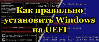
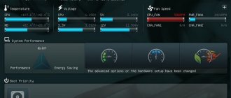
We perform BIOS tuningPC HEALTH STATUS PC Health Status section contains readings from voltage, temperature and cooling system fan speed sensors. Reset Case Open Status is responsible for resetting the state of the case opening sensor. If your PC is not assembled at a factory of a large brand (Dell, HP, etc.), you most likely do not have such a sensor and this parameter will not be useful to you. Information about the voltages on different subsystems of the computer will tell you little if you are not a specialist. But the points +3.3v +12v are of great importance: these are real voltages on the corresponding channels of the power supply. If the nominal value deviates by more than 10%, the system may operate unstably; in addition, if the nominal value is exceeded, overheating and failure of key components—the motherboard, hard drives, and video cards—may occur. Most often, increased voltages indicate insufficient power of your power supply. CPU Warning Temperature item allows you to set a processor temperature threshold, if exceeded, the system will warn the user with a piercing two-tone siren. This feature was once critical to the survival of the processor: when heated above 90°C, semiconductors begin to fail, and cases of “baked” processors were not uncommon. Modern processors independently monitor their temperature and simply reduce the clock frequency when overheating. Thus, even a cooler that falls off its mount will not destroy your expensive Intel Core i7 - you will soon find that the OS takes more than half an hour to load, and you will take your PC for repair. Nevertheless, this function is still useful: it will let you know that the power of your cooling system is insufficient, and you need to either upgrade it, or unoverclock the processor, or change the climate to a less hot one. The following points concern alarms about cooling system fan failures. For obvious reasons, you should not turn on a fan failure alarm, which your PC simply does not have (you can determine this by the zero speed value) in the information fields above. An important parameter , CPU Smart FAN Control , allows you to significantly reduce the noise generated by the PC: when this parameter is activated, the rotation speed of the processor fan will be adjusted in accordance with the temperature of the processor, that is, when the system is not heavily loaded, the computer will make noticeably less noise. There are also “pitfalls” in this mode: not everyone likes changes in the noise level while working with a PC; even noise that does not change in frequency and strength is psychologically much less noticeable than noise that changes over time.
MB INTELLIGENT TWEAKER (MlT) MB Intelligent Tweaker item was left for dessert, despite the fact that it is placed in first place in the CMOS Setup menu. The fact is that MIT is responsible for a rather risky operation - system overclocking .
This section is called differently in each board, but it is not difficult to recognize it by such parameters as the clock frequency multiplier and processor supply voltage, memory request latency parameters, etc. Note If you perform illiterate actions in this section of CMOS Setup, it is very easy to ensure that your system refuses to start. Moreover, the motherboard, processor or memory may simply fail. We strongly recommend not touching these settings unless you are a specialist or enthusiastic overclocker.
The overclocking technique is beyond the scope of this material, so we will not describe it in detail; we will only tell you about the main parameters. Robust Graphics Booster function can be confusing - its purpose is quite unusual and you won’t find it on most motherboards. The fact is that it serves to increase the clock frequency of the video core integrated into the motherboard. In modern systems, such video cores are practically not used - and this task has been taken over by the central processor. CPU Clock Ratio is perhaps the most popular parameter during overclocking. It is responsible for the processor multiplier and reflects the relationship between the processor bus clock speed and the internal processor clock speed. By multiplying the bus frequency (CPU Host Frequency) by this multiplier, you get the processor clock frequency (CPU Frequency). Overclocking in this way is the safest, since it only affects the processor itself, but precise frequency adjustment cannot be achieved in this way; you will have to use more subtle tools. Note also that many processors and chipsets do not allow changing the processor multiplier; in this case, this parameter will be absent in CMOS Setup or its value will not affect anything. The main way to overclock memory is to increase its clock speed. In order for the memory to operate reliably at a higher frequency, you can slightly increase the voltage. A much more subtle option is to configure timings - parameters responsible for delays in memory requests. Reducing the timing leads to increased performance and decreased stability, and it is often very difficult to find the fastest workable values. However, you can almost always improve system performance by fine-tuning the timings. The fact is that the manufacturer leaves some margin of safety when setting nominal timings. and most manufactured memory modules are capable of more if you try to overclock them. CPU Host Clock Control allows you to adjust the processor bus frequency over a wide range. This parameter should be handled very carefully and should not be increased by more than 10-15% of the nominal value (in our case, 333 MHz). Excessively increasing the bus frequency is guaranteed to make it impossible to start the system without clearing the BIOS parameters. The second important section in the overclocking menu, DRAM Performance Control , provides a lot of opportunities to speed up the memory subsystem.
Standard parameters for memory are recorded in a special SPD chip located on the memory module; it is these data that the system is initially guided by. Typically, BIOS developers allow the user to change the settings as desired. — — —
Rest
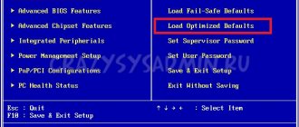
Load Fail-Safe Defaults is responsible for loading parameters for normal computer operation. Load Optimized Defaults Provides maximum performance. In Set Supervisor Password and Set User Password, you set, change, or disable the password for logging into Bios Phoenix and gaining full access to BIOS settings. Supervisor and User differ in the degree of accessibility to BIOS settings. Using Save & Exit Setup, settings are saved and the BIOS is exited; Exit Without Saving - exit without saving changes.
Text of the book “BIOS and PC fine-tuning. Easy start"
■ F5
– restoring previous values for the selected partition: the values that were at the time of entering the BIOS Setup program will be returned (in some BIOS versions this key is used to set default values);
■ F6 —
setting default values for the selected section (
Load Fail-Safe Defaults command);
F5
or
F9
keys may be used for these purposes (for example, in AMI BIOS);
■ F7
– setting optimized values for the selected section (
Load Optimized Defaults command);
■ F10 —
Exit BIOS Setup with saving all changes made, and you need to confirm the actions using the
Y
and
Enter keys.
ATTENTION
Depending on the BIOS, the function keys may have different meanings, so it is best to check your motherboard manual or the prompt at the bottom of the screen before using them.
Exit BIOS Setup
To exit BIOS Setup, there are two options:
■ exit with the cancellation of all changes made;
■ Exit and save all changes made.
To exit and cancel all changes made, select the Exit Without Saving command in the main window,
Quit Without Saving (Y/N)
usually appears (Fig. 2.6), and press the
Y
and
Enter keys.
You will exit BIOS Setup and the computer will continue to boot.
Rice. 2.6.
Confirmation window for exiting BIOS Setup with cancellation of all changes made
Exit with discard changes should be used in the following cases:
■ when you did not plan to make any changes, but only viewed the current parameter values;
■ if you are not sure of the correctness of actions or accidentally changed one or more parameters.
To exit and save all changes made, select the Save & Exit Setup
– a window will appear with the message
SAVE to CMOS and EXIT(Y/N)?
(Fig. 2.7).
Press the Y
and
Enter keys,
all settings will be saved and the computer will continue to boot.
If you change your mind about making changes to CMOS, press N
and
Enter
or use the
Esc key.
Rice. 2.7.
Confirmation window for exiting BIOS Setup with saving changes made
Use exit with saving changes only if you are confident in the correctness of your actions and did not make mistakes or oversights when editing the parameters.
If your computer uses the BIOS setup utility with a menu bar at the top, select Exit from the main menu.
Exit Without Saving
and
commands described above .
Examples of editing BIOS Setup parameters
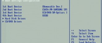
Imagine you need to boot your computer from a bootable CD, such as a Windows distribution. To do this, you need to change the boot order in the BIOS so that the CD drive is the first boot device in the list.
The sequence of actions may be as follows.
1. Restart your computer.
2.
During the initial stages of the self-test (POST), press the BIOS entry key (usually
Delete
or
F2).
Wait for the main BIOS Setup window to appear. If you pressed a key at the wrong time and the operating system loaded instead of entering Setup, restart the computer again and try again.
3. Using the cursor keys, select the desired section in the main program window, in our example it is Advanced BIOS Features,
and press
Enter.
4. Remember, or better yet, write down the current values of the parameters of the selected section, so that in case of careless actions you can return the original values of the changed parameters.
5. The parameter that determines the first boot device is usually called First Boot Device,
so select it from the list.
It will need to be set to CD-ROM
or
CD/DVD.
You can change the value of the selected parameter in one of two ways:
• press the Page Up/Page Down
(or +/– on the additional numeric keypad) until the desired parameter value is set;
• press Enter, select the desired value in the window that appears (Fig. 2.8) and press Enter again; This method is more convenient, but is not supported by older BIOS versions.
Rice. 2.8.
Editing a parameter in a pop-up window
6. Exit to the main program window using the Esc key.
7. To exit BIOS Setup and save the changes made, select the Save & Exit Setup command, and in the window that appears, confirm your intentions by pressing the Y and Enter keys.
ATTENTION
Never exit BIOS Setup with saving changes if you have touched any parameter through carelessness or curiosity. In this case, you need to exit BIOS Setup and cancel all changes made, then log in again and edit the desired parameter again.
8. Test your changes by booting from the CD.
9. Restart the computer again and return the First Boot Device parameter to its previous value, then try to boot the computer in normal mode.
On boards from ASUS, ASRock and some other manufacturers, the main BIOS Setup window is slightly different from the one discussed above.
For BIOS versions with a horizontal menu bar, the sequence of actions to change the boot device will be slightly different.
1. Restart your computer and enter BIOS Setup.
2. Using the <– and —> keys, select the Boot section in the main menu of the program. Remember or write down the current parameter values.
3. Using the V and ^ keys, select the First Boot Device (1st) parameter and set it to CDROM (CD/DVD) using one of the methods described above (Fig. 2.9).
Rice. 2.9.
Editing the list of boot devices in AMI BIOS
4. Using the <– and —> keys, go to the Exit section and execute the Exit & Save Changes command. Confirm your actions by pressing Enter in the window that appears.
5. Try booting from the CD, then return the First Boot Device parameter to its previous value.
Tips for working safely with BIOS Setup
Working with BIOS Setup is associated with a certain risk, since if the parameters are changed unsuccessfully or carelessly, the system may become unstable or not function at all. There are a few simple tips that will help reduce the possible risk to a minimum.
■ Avoid experimenting with the BIOS at all on computers that process or store important information. Before setting up your system using the BIOS, be sure to back up your important data.
■ Before changing parameters, always remember, or better yet, write down their old and new values. This will allow you to return the system to its previous state if it becomes unstable with the new settings. You can, of course, photograph the BIOS Setup screens with a digital camera.
■ Do not change settings that you do not know. If you do not find a description of the parameter you are interested in in the book, refer to the motherboard manual.
■ Do not edit multiple unrelated parameters in one session. If the system crashes, it will be very difficult to determine which of the changed settings caused the problem, and you will have to start all over again.
■ Do not overclock your computer without proper preparation. Read more about overclocking in section 3.
■ Do not use the Hard
Disk Utility, which is designed for low-level formatting of older hard drive models and is found in many older BIOS versions. Please be aware that low-level formatting for IDE hard drives may damage them.
Unfortunately, in real life it is not always possible to foresee everything, and it happens that after changing the BIOS settings, the computer stops working normally or does not work at all. If the reason is only due to incorrect setting of BIOS parameters, then the system can be brought back to life in several ways.
■ If you can enter BIOS Setup after restarting the computer, you need to reset the edited parameters to their previous values. Please remember that all changes must be recorded in advance.
■ If you have not written down the changes you have made, you should not change all the parameters in a row, this will only make the situation worse. In this case, you can try to restore the system by loading the default settings using the Load Fail-Safe Defaults command.
After this, you will need to reconfigure the system for optimal operation.
■ Sometimes the computer may not turn on at all only due to incorrect BIOS settings. In this case, you will have to reset the CMOS contents (see Section 3).
Main sections of BIOS Setup
Most versions use the classic interface of the BIOS Setup main window, in which the sections are arranged in two columns (see Fig. 2.4). Although each motherboard model has its own unique set of parameters, the names of the main sections of BIOS Setup, as a rule, do not change. Let's briefly look at the purpose of the main sections of AwardBIOS and AMI BIOS.
Standard CMOS Features (Standard CMOS Setup)
As the name suggests, this section contains standard computer settings, which usually include disk drive parameters, date and time settings, etc. You can also find information about the amount of installed RAM and other information about the system.
Advanced BIOS Features (BIOS Features Setup)
The name of the section can be translated as “advanced BIOS settings,” which usually includes computer boot parameters, general parameters of the processor, chipset, keyboard, cache memory and other devices.
Advanced Chipset Features (Chipset Features Setup)
The section describes the chipset settings, which means its content depends on the type of chipset on which the motherboard is built. To be more precise, there are parameters related to the northbridge of the chipset and determine the operation of the RAM, processor, video system, AGP and PCI Express buses and some other devices. The settings in this section can significantly affect the speed and stability of the system, so they should be changed with extreme caution.
Integrated Peripherals
This section contains parameters for various integrated peripheral devices that are supported by the south bridge of the chipset: floppy and hard disk controllers, sound and network adapters, serial, parallel and USB devices, etc. The composition of the settings in this section depends on the composition of the peripheral devices in a particular system .
Power Management Setup
This section sets power supply parameters and energy saving modes. You can set your computer to automatically go into low-power conditions and force it to return to a working state when certain events occur.
PNP/PCI Configurations
The settings in this section control how resources are distributed among peripheral devices. Typically, this function is entrusted to the system, leaving the automatic resource allocation configured by default.
PC Health Status
All modern motherboards are equipped with sensors for monitoring operating temperatures, voltages and fan speeds. Their current readings are displayed in a separate section of BIOS Setup called PC Health Status
or
H/W Monitor.
Sensor readings are used in automatic overheating protection systems, and the corresponding parameters are set to determine the protection threshold.
Frequency/Voltage Control
In this section, operating frequencies and voltages are set for the processor, chipset, RAM, video adapter, etc. With default settings, all frequencies and voltages in modern computers are adjusted automatically, which ensures reliable operation of the system. If you change the parameters of this section manually, you can overclock, that is, force the processor, memory and other components to operate at higher frequencies (see Section 3).
Load Fail-Safe Defaults (Load BIOS Setup Defaults)
The command resets all BIOS settings to default values. In this case, the safest values of all parameters are set, ensuring high stability of the system. When you select this item, a window usually appears in which you need to confirm the selected action by pressing the Y key (Fig. 2.10).
Rice. 2.10.
Window confirming loading of default parameters
Load Optimized Defaults (Load High Performance)
The command sets BIOS settings that ensure optimal system performance while maintaining system stability. Depending on the specific motherboard model, these values may vary, but, as a rule, optimized settings differ from the default settings by faster POST, faster RAM operating modes, faster bus operation, and some other parameters.
Sometimes the optimized parameters are not compatible with the existing hardware, and the system may become unstable after this command. In this case, you should return to the default settings using Load Fail-Safe Defaults,
then configure the system for optimal operation manually.
Set Supervisor Password, Set User Password
The commands set respectively administrative and user passwords for entering the BIOS or booting the computer (see Section 5).
BIOS setup utility with horizontal menu bar
Some board manufacturers, such as ASUS or ASRosk, use a different view of the main BIOS Setup window, in which the menu bar is located at the top (Fig. 2.11). This interface was originally used in PhoenixBIOS; you can also find versions of AMIBIOS and even AwardBIOS made in this style. This kind of organization is more suitable for novice users, and you will learn about the purpose of the main sections later.
Rice. 2.11.
BIOS setup main window with horizontal menu bar
Main
Here are the main BIOS settings, according to the developers :
date and time, disk drive parameters and system information.
Main
is almost a complete analogue of the
Standard CMOS Features section.
Advanced
This section is usually the most voluminous in terms of the number of parameters and consists of several subsections (Fig. 2.12). Here you can find settings for the processor, chipset, memory, video system and peripheral devices. Compared to the classic interface, the Advanced
includes the contents of the
Advanced Chipset Features, Integrated Peripherals, Frequency/Voltage Control, PNP/PCI Configurations sections
and some parameters from
the Advanced BIOS Features.
Sometimes
BIOS
allocate some of the parameters from
Advanced
to a separate section, thus increasing the number of items in the main menu.
Rice. 2.12.
The Advanced section usually consists of several subsections
Power
IN
This section, similar to the
Power Management Setup section,
sets power parameters.
This also usually includes parameters for monitoring operating voltages, temperatures and fan speeds (as in H/W Monitor).
Boot
Here you can find parameters that determine the order in which boot devices are polled and other boot settings. In addition, there may be parameters for managing passwords, but in some versions they are placed in a separate Security
(see Fig. 2.11).
Exit
This section (Fig. 2.13) usually contains the following commands:
■ Exit Saving Changes—
exit with saving all changes;
■ Exit Discarding Changes—
exit with the cancellation of all changes made;
■ Load Setup Defaults—
setting default values;
■Discard Changes
– canceling the changes made.
Rice. 2.13.
Exit section
After selecting any of these commands, a window usually appears in which you need to confirm or cancel its execution.
Diagnostics, repair and overclocking of a computer using BIOS
Using the material in this section, you will learn how to diagnose and troubleshoot computer problems, as well as overclock your system. By overclocking your computer, you can squeeze maximum speed out of your equipment. True, overclocked components will work in conditions close to extreme. This can also have negative consequences, so overclocking should be approached carefully and carefully.
BIOS Beeps and Troubleshooting Tips
Initial testing of the computer is usually accompanied by one short beep, which indicates the successful completion of the POST procedure and the operating system is ready to boot. If a serious error is detected, the system will stop running with audible alarms and/or messages displayed on the monitor screen. Beeps are used when a fault prevents the system from displaying an error message on the screen. They can also be used to further attract the user's attention when displaying visual messages.
In table 3.1 and 3.2 show the meaning of sound signals for AMI and Award BIOS. It should be noted that some motherboard manufacturers may change the meaning of signals or add new ones. If you hear an unknown signal, try looking for its decoding in the instructions for the motherboard or contact your manufacturer's technical support service.
If your computer won't boot, with or without a specific beep sound, or no image appears on your monitor screen, you can use the following troubleshooting tips.
1. Restart your computer using the Reset button on the system unit. Sometimes you need to completely turn off the computer and turn it back on after a while.
2. If rebooting again results in an error, turn off the computer and carefully check that the devices are connected correctly, the contacts in the slots and connectors are secure, the integrity of the connecting cables and cables, etc.
3. The computer may not boot due to unsuccessful overclocking or incorrect setting of some BIOS parameters. In this case, you should reset all BIOS settings using a jumper on the motherboard or another available method.
4. If checking the quality of connections and resetting the BIOS does not produce results, try replacing the suspected device. Sometimes it can be determined incorrectly by the values of the audio signals, since most devices are interconnected and influence each other.
5. When replacing the problematic device is impossible or does not produce results, try booting the system with a minimum number of devices, disconnecting all drives, expansion cards and peripheral devices.
ATTENTION
Do not forget that you can connect or disconnect devices only after completely disconnecting the computer from the network.
6. If the system starts in a minimal configuration, try connecting some kind of boot device (floppy drive, hard drive or CD-ROM) and boot the operating system. If successful, connect all other components in series and check the operation of the system.
Table 3.1.
AMI BIOS beeps
Table 3.2.
Award BIOS beeps
Error messages
If the system initialized the video adapter during boot, messages will be displayed on the monitor screen during boot. If a critical error occurs, the process will stop and a corresponding message will be displayed. If the error is not critical, then a message about it will be displayed, but the download can continue.
In table 3.3 provides explanations of the main error messages for AMI, Award and Phoenix BIOS.
NOTE
Some newer motherboard models use voice error messages during POST. For example, in motherboards manufactured by ASUS this technology is called ASUS POST Reporter, and in Albatron boards it is called Voice Genie.
Table 3.3.
Decoding Award BIOS and AMI BIOS error messages
POST codes
Before each operation, the POST program writes its code to a special diagnostic port. And if the cause of the system failure could not be determined by sound signals or messages on the screen, you can try to find out the POST error code and decrypt it.
You can determine the POST code that is causing the error using one of the following methods.
■ Some board models have a built-in POST code indicator. These include EPoX boards, as well as some models from ABIT and Chaintech.
■ You can also find boards where POST codes are displayed in the corner of the screen, but this method does not allow diagnosing errors that occur before the video adapter is detected.
■ If the board does not have built-in means of displaying POST codes, you must use a special POST board that is inserted into the PCI slot.
To decrypt POST codes, you need to find a table of POST codes for your BIOS version. Sometimes it is in the instructions for the board, otherwise you should look for it on the BIOS manufacturer's website. A good Russian-language resource containing information about POST codes is located at icbook.com.ua .
Resetting BIOS Settings
All BIOS versions have a command that sets parameters to default values - this is Load BIOS Setup Defaults
or
Load Fail-Safe Defaults.
You can also reset the BIOS settings using a jumper on the motherboard. This procedure is also called “resetting” BIOS settings and allows you to achieve the most stable operation of the system. It can restore normal functioning of the computer when problems in its operation are associated with incorrect parameter values. It is also necessary when updating the BIOS and in some other cases.
Resetting settings using BIOS Setup commands is the simplest and most accessible method, but in some cases it is impossible to use it. Here are the most common situations.
■ It is necessary to remove the unknown password to enter BIOS Setup or boot the computer.
■ The computer does not boot at all due to unsuccessful overclocking or incorrect BIOS settings.
Before you open the system unit and reset the CMOS using a jumper, try one simple method supported by many modern motherboards: turn on the computer's power while holding down the Insert key,
and if the system starts, click
Delete
to enter BIOS Setup and reset settings.
For almost all boards, you can reset the settings using a jumper. You can find out about its location in the manual for the motherboard; there are also tips on how to reset it. On most boards, the jumper is located next to the battery and is labeled Clear CMOS.
The sequence for resetting the BIOS using a jumper usually looks like this.
1. Turn off the computer and disconnect power from the system unit.
2. Open the cover of the system unit and set the jumper to the Clear CMOS position for a few seconds.
3. Return the jumper to its original position, reassemble and turn on the computer.
ATTENTION
Do not move the jumper while the power is on, and do not turn on the computer if the jumper is in the Clear CMOS state.
On most motherboards, to clear the CMOS, you need to move the jumper from position 1-2 to position 2-3. Sometimes there are only two contacts that need to be closed for a few seconds (Fig. 3.1). There is also a microswitch for clearing CMOS.
Rice. 3.1.
Two-pin jumper for clear CMOS
If you don't have a jumper or switch to clear CMOS, you can try this method.
1. Turn off the power, open the system unit and remove the battery from the socket. If it is soldered to the motherboard, this method will not work.
2. After 10-20 minutes, insert the battery back and start the computer. If these steps do not clear the CMOS, you can try leaving the motherboard without a battery for one day.
Reasons to update the BIOS
On almost all modern boards, the BIOS code is written into a flash memory chip, so updating the BIOS version, or, in other words, “reflashing” it, is quite simple. On the other hand, updating the BIOS is a very important operation, and it should be performed only in cases where it is really necessary. Here are some good reasons.
■ You need to install a new processor on the motherboard, support for which only appeared in the updated BIOS version.
■ You need to connect a larger hard drive to the system board than the BIOS version allows.
■ You need to enable additional chipset features that were not enabled in the original BIOS.
■ If the system is slow or unstable due to errors in the BIOS code. However, it should be remembered that many other factors affect the speed and stability of the system, so you first need to check the current BIOS settings, hardware operating parameters and the correctness of drivers, operating system settings and application programs.
If there are no compelling reasons to update the BIOS, it is better to avoid this operation. After all, then you will have to re-check and, if necessary, edit the BIOS settings, and in some cases, reconfigure the operating system or even reinstall it.
To update, you should perform several preparatory steps: find a new BIOS version, prepare a floppy disk and take care of system stability. Read about all this below.
Finding a new BIOS version
The first task that needs to be solved when updating the BIOS is to download the file with the updated firmware from the board manufacturer's website. To do this, you need to know the manufacturer's name and board model. If the board comes with instructions, then all the necessary information can be found from it. True, some manufacturers print general instructions for several models, and in such cases the board model needs to be clarified.
If there are no instructions for the board, it is best to use one of the special diagnostic utilities to determine the manufacturer and model.
■ SiSoftware Sandra (
www.sisoftware.co.uk
).
After installing and launching the program, open the
Summary information section,
which contains basic information about the processor, motherboard and chipset. For detailed information, visit the motherboard section, where you can find the BIOS version number and other useful parameters.
■ EVEREST (
www.lavalys.com
).
This program is completely similar to SiSoftware Sandra, only the section names may differ slightly. Its advantage is the indication in the reports of direct links to the websites of the manufacturers of the detected equipment (Fig. 3.2).
You can also find out the board model by simply examining it. Open the cover of the system unit and find the model marking, which is painted directly on the board (Fig. 3.3). Many boards also have a model label affixed to the lowest expansion slot or other location.
After determining the board model, you need to go to its manufacturer’s website. You can find out its address from the instructions, the EVEREST program, or use search servers, for example www.google.ru or www.yandex.ru .
The firmware for your model should be found on the Download page
,
which can sometimes be located in the Technical Support section
.
Rice. 3.2.
The EVEREST program has direct links to manufacturers' websites
Rice. 3.3.
Manufacturer name and model are printed between PCI slots
Find your board model and go to the page with a list of drivers and BIOS updates. This should be the version that is already installed on your system, and you need to study the changes made in the new versions. To update, download the latest version of the BIOS; in addition, you can download the firmware program recommended by the manufacturer (if it is not in the archive with the firmware itself) and view the update instructions.
ATTENTION
To update, you need to find a file with BIOS code that is designed exactly for your motherboard model. Using a BIOS version from another, even a very similar model, can lead to system inoperability.
Preparing a boot diskette
In most cases, the BIOS is updated in the MS-DOS operating system environment, which must be loaded from a floppy disk. To create a bootable MS-DOS floppy disk in Windows XP, follow several steps.
1. Insert a blank floppy disk into the drive.
2. Open the My Computer window,
Right-click on the
A:
and select
Format.
3. In the window that appears, check the Create MS-DOS boot disk
(Fig. 3.4), click the
Start button,
confirm your actions by pressing
OK
and wait until the procedure is completed.
In operating systems of the Windows 9x family, a boot floppy disk can be created as follows.
1. Open the Start program window,
Click
Start ► Run,
type
format a: /s
and click
OK.
2. Following the formatting program's instructions, insert the floppy disk into the drive and press Enter
to start formatting.
3. When prompted for the volume label, simply press Enter.
and also
N
if you are not going to format several disks in a row.
Rice. 3.4.
Creating a boot floppy disk in Windows XP
You can create a bootable floppy disk in MS-DOS using the same method, but type the format a: /s command at the command line prompt.
ATTENTION
Do not use floppy disks with additional drivers and utilities that are launched using the autoexec.bat and config.sys files to boot the system. To update, you need stability above all, so use floppy disks with a minimum set of system files. If the compressed disk driver drvspace.bin was written to it when you created the floppy disk, delete it.
NOTE
Although most board manufacturers recommend booting your computer from a floppy disk, you can also use other storage media, such as a CD or flash drive. You can use Nero Express to create a bootable CD, and you can usually use the hardware manufacturer's utilities to burn the system to a flash drive.
Ensuring system stability
Before updating, you should ensure that your system is as stable as possible. Here are some important recommendations.
■ First of all, you need to ensure reliable power supply, it is best to use an uninterruptible power supply (UPS).
■ Try to exclude the possibility of accidental pressing of keyboard keys and system unit buttons, and provide for other surprises.
■ If you are working with floppy disks, check their quality in advance. Crashes can cause you a lot of trouble.
■ Ensure system stability using BIOS settings. Overclocking the processor, memory and other components when updating is unacceptable. The best thing to do is reset all BIOS settings.
Award BIOS update
To flash systems with AwardBIOS, use the Awdflash.exe utility (it may have another name, for example Award.exe). It allows you to update the BIOS in two ways: in dialog mode and using command line settings.
Boot device selection
This is one of the frequently used actions that the user has to deal with. By default, the operating system is searched on the HDD or SSD. But when reinstalling the OS, the flash drive must be scanned. This is done as follows:
- After turning on the computer, the user presses F10. This can be any other key, depending on the computer model.
- The BIOS window appears. You need to go to the section and configure the download priority.
- Moving is done using the right or left arrow on the keyboard. When the desired tab is highlighted, you must press Enter.
- A window with settings appears. Here you need to configure the boot order of devices.
- First Boot Device selects the device that contains the operating system. If it is a flash drive, the value should be USB-HDD, if the drive is CD-DOM/DVD-ROM.
Program description
PC Health Check Windows 11 is a standalone utility that allows users to check the ability to run a new operating system on a personal computer or laptop. The utility scans the hardware components of the device and provides the user with a detailed report.
The performance of the device is assessed according to several criteria at once, so if any element is incompatible with Windows, the application indicates specific reasons and ways to solve them.
Software for checking Windows 11 is distributed only through the official website of the developer company.
To use the program, you must create or sign in to a Microsoft account. Otherwise, the functionality will not be available.
User interface
Setting a BIOS password
When several people use the computer and you need to limit the number of users who can make changes to the BIOS settings, a password is set. There are two types of password: supervisor and user. The first allows you to change settings, the second - only view.
There are separate sections for setting a password. Set Supervisor Password is used to set the administrator password, Set User Password is used to set the user password. The transition to the corresponding menu items is carried out using arrows, and the Enter button is used to set a specific value. For the changes to take effect, you must save them before exiting using F10. To enable the use of a password, select Clear Password.