The UEFI specification , formerly known as the Extensible Firmware Interface (EFI), defines the interface between the operating system and the microcode(s) that control the hardware. In other words, UEFI is an interface that sits “on top” of the computer’s hardware components, which, in turn, operate on their own firmware (microcode).
In the name UEFI itself, the definition of “extensible interface” suggests that it is a modular system that can be functionally easily expanded and upgraded.
For greater understanding, UEFI compared to BIOS is, roughly speaking, a new type or the next generation of firmware, and it is no longer limited only to x86 personal computers (IBM PCs), but also claims to be an all-platform standard. However, unlike BIOS, UEFI is based on a fundamentally new code topology called “driver-based”.
- The main purpose of EFI is to replace aging (losing relevance) BIOS technology and the limitations associated with it.
- The main goal of UEFI development is to standardize the interaction of the operating system with platform firmware during the boot process. In the classic BIOS, software interrupts and I/O ports were the main mechanism for interacting with hardware during the boot phase, but modern systems are able to provide more efficient I/O operations between hardware and software.
- The main task of EFI is to correctly initialize the hardware and transfer control to the operating system loader. In this regard, the task is not very different from the task of a traditional BIOS, but the algorithms are fundamentally different.
UEFI can be safely called an independent miniature operating system, which is an interface between the main user operating system running on the computer and the hardware microcode.
Let's now take a short excursion into the history of personal computers in order to understand the reasons that led to attempts to replace the standard BIOS with something fundamentally new.
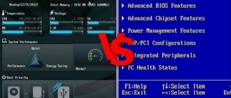
Good old BIOS
The basic principles of the functioning of the BIOS (basic input-output system) for personal computers were defined back in the late 70s of the last century. Over a fairly long period of time that has passed since then, the computer industry has developed rapidly, which led to the fact that at certain stages the BIOS capabilities were not enough, since the devices produced by manufacturers had new technologies on board, often incompatible with current BIOS versions. To avoid such problems, developers sometimes had to significantly modify the BIOS code, but a number of restrictions have remained unchanged to this day. And, if initially the BIOS architecture was quite simple, then over time it inevitably became more complicated, adapting to more and more new technologies, therefore, at a certain point it began to resemble a pile of various kinds of outdated code that did not interact well with each other. The limitations that can still be found in BIOS code today are explained by the need to maintain compatibility with the basic functions necessary for the functioning of older software. All this has led to the fact that the BIOS has essentially become the most outdated component of modern PCs. At the moment, the BIOS does not meet the requirements of the latest equipment and has the following disadvantages:
- 16-bit code, real mode. The BIOS is written in assembly language and operates on 16-bit code in real mode of the processor with its inherent limitations, the most significant of which is the limitation of the memory address space of 1 Megabyte.
- Lack of access to 64-bit hardware. The BIOS is not capable of directly interacting with the 64-bit hardware that currently dominates the market.
- Lack of a uniform standard. There is no single specification for BIOS - each manufacturer offers its own implementation variations.
- Complexity of development. The problem is that for almost every new motherboard model, the manufacturer develops its own version of the BIOS, which implements the unique technical features of this device: interaction with chipset modules, peripheral equipment, etc. BIOS development can be divided into two stages. At the first stage, a basic version of the firmware is created, which implements those functions that do not depend on the specifics of the equipment. The developers of such code are well known, these are companies such as American Megatrends (AMIBIOS), Phoenix Technologies (+ the legendary Award Software (AwardBIOS) acquired by it) and some others. At the second stage, programmers from the motherboard manufacturer are involved in BIOS development. Here the basic assembly is modified to suit the specifics of each specific board model, its features are taken into account. After the motherboard enters the market, work on the firmware continues, updates are regularly released that fix errors, add support for new hardware (for example, processors) and sometimes even expand the functionality of the firmware.
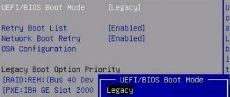
All these, as well as some others, shortcomings of the traditional BIOS model led to the fact that a coalition of hardware and software manufacturers began working on the creation of the UEFI specification. Starting, according to my own observations, around 2010, the UEFI specification began to be massively introduced into all newly released motherboards from leading manufacturers, so at the moment it is almost impossible to find a new computer with a traditional BIOS. However, you shouldn’t be too upset about this, since many manufacturers maintain compatibility with the functionality of traditional BIOS in their motherboards. For example, support for traditional boot mode using MBR is a very important point. For this purpose, a UEFI BIOS emulation mode module was developed, which is called Compatibility Support Module (CSM). True, I believe that over time, fewer and fewer manufacturers will support this mode in their firmware.
New security technology
Where the new UEFI BIOS system is ahead is in the level of security. The fact is that there are viruses that can penetrate the microcircuit where the BIOS algorithms are written. After which, it becomes possible to load the OS with extended user rights, which opens up the widest possible opportunities for a hacker. In turn, the new solution from Intel implements secure boot - UEFI provides an appropriate algorithm called Secure Boot.
It is based on the use of special keys, which must be certified by the largest brands in the IT market. However, as experts note, in practice there are not too many such companies yet. In particular, with regard to the support of the corresponding option by operating system manufacturers, it is fully provided only by Microsoft and only in Windows 8. There is also information that compatibility with the new security system is implemented in some Linux distributions.
Benefits of UEFI
Here I would like to define the advantages of the UEFI interface:
- Support for large storage media (disks). UEFI owes its support for large disks to a new partition table standard called GPT (GUID Partition Table). The traditional BIOS boot method used the Master Boot Record (MBR) boot sector, which contained a partition table that described the placement of disk partitions. Partition table entries in the MBR have one significant drawback: the number of the first sector of the beginning of the partition in LBA format (offset 08h from the beginning of the partition entry) has a width of only 4 bytes (32 bits), respectively, only 4 billion sectors can be addressed. And this, with the “classic” sector size of 512 bytes, is only ~2 terabytes of disk space. UEFI, using GPT, makes it possible to address disks up to 18 exabytes.
- Direct support for file systems and partition tables. UEFI has modules for supporting file systems and partition tables, that is, it can work with both partition tables and file systems directly. The specification implies support for the GPT partition table, FAT12, FAT16, FAT32 file systems on hard drives and the ISO9660 file system on CD/DVD drives. This saves us from having to write bootstrap code (similar to MBR), which will load bootloaders of various stages in a chain.
- No other traditional MBR restrictions. For example, you no longer need to squeeze bootstrap code into a tiny 512-byte sector. You can focus on writing a single loading module that will combine all the necessary stages.
- Platform-independent hardware drivers. UEFI has access to the computer's hardware through platform-independent drivers. The device manufacturer only needs to write one version of the driver for all platforms (x86, ARM, Itanium, Alpha), and this greatly simplifies development and speeds up the process of identifying errors. The UEFI specification describes the interaction of UEFI drivers with the operating system, thus, in the case when the OS does not have a driver, for example, a video card, but in UEFI it is present, loaded and functioning, the OS has the ability to output data to the monitor using standard UEFI interfaces.
- Support for TCP protocol stack: IPv4/IPv6. Allows you to use rich networking capabilities directly from the UEFI interface. Now you can develop various downloads using http/ftp protocols; a download immediately comes to mind indicating the URL where a regular EFI module or a full-fledged ISO image is located. It has become possible to bypass what has already become the only possible option, loading over the network using PXE/TFTP. Some, especially advanced implementations, may implement support for PXE over IPv6.
- Support for traditional BIOS model. UEFI does not require a classic BIOS, but many manufacturers embed BIOS emulation code to support older operating systems. This module is called the Compatibility Support Module (CSM). The CSM includes a 16-bit module (CSM16) implemented by the BIOS manufacturer and a layer that links the CSM16 to the instrumentation (interface and hardware). Compatibility implies support for booting via MBR and support at the code level for software interrupts (int 10h - video service, int 13h - disk service, int 15h - service functions, int 16h - keyboard service, int 18h - ROM-BASIC service, int 19h - bootstrap loader service). Therefore, those OS and software that needed the good old BIOS to work like air can easily work on machines with UEFI.
- Intuitive UEFI interface. The so-called “ease of control”. This is a rather controversial point; it is impossible to unequivocally classify it as a plus or a minus. It is alleged that BIOS management was not intuitive, presenting a poorly documented, ascetic text interface that only a computer-savvy user could understand. In contrast, many UEFI shells support a graphical interface and a mouse, which are simply not implemented in most BIOSes. However, if my memory serves me correctly, back in the 90s I observed attempts to implement mouse support in the BIOS from (I think) Phoenix. The interface itself can be graphical, in the opinion of some - more friendly and intuitive for the majority, but it can also be traditional, that is, similar to a classic text one, it all depends on the preferences of the developer and the positioning of the equipment. It is possible to support multiple languages.
- UEFI speed. It is claimed that the UEFI code runs faster than the traditional BIOS code (although it is written in C), due to the fact that it is entirely written “from scratch”, without the need to “drag” a train of outdated code to support various non-standard hardware and various logical anachronisms.
- OS loading speed. It is claimed that booting with UEFI is significantly faster. This is achieved by parallelizing the initialization of devices, as opposed to the BIOS, which initialized the equipment sequentially, as well as reducing startup time due to the absence of the need to search for the bootloader by enumerating all devices (the bootloader is specified in UEFI and called directly). I am inclined to believe it, since I cannot confirm or deny it at the moment. However, if you measure how much time it takes on my old machine on a Celeron 450/GA-G31M-ES2L with an SSD from the moment it is turned on until the authorization window for the optimized Windows XP appears, it will only be 23 seconds. This will probably not be enough for certain categories of devices.
- UEFI is a mini OS. You can, of course, call UEFI a miniature operating system, and this, in part, will be fair, but it would be more correct to consider it a virtual platform that provides interfaces to equipment. You can only work in the console, or you can write a full-fledged graphical interface. UEFI, if there are modules of the necessary functionality, can, for example, help understand problems loading the main OS, or perform other service functions.
- Additional software modules. Immediately before loading the operating system from the UEFI media, it allows you to launch your own UEFI modules and drivers for general purposes: for working with the network, disk (archiving/backup/antivirus), configuring parameters, testing equipment. Obviously, with the popularization of the standard, the list of UEFI applications will only expand. Nowadays you can even write a full-fledged game, develop your own console for service needs in the form of a separate UEFI module (example: shell.efi), an Internet browser, provide work with media data (watching movies, listening to music), and organize disk backups.
- UEFI contains a built-in download manager. That is, it implements its own OS code loader, which is very functional and can act as an analogue of the multi-loaders of several operating systems familiar to us from the not so distant past.
- I/O block size. In UEFI, when reading, a special EFI I/O block size is used, which allows reading 1 MB of data (in the BIOS the limit is 64 KB).
- Safety. Supposedly UEFI is protected from malicious code during the boot phase. It is alleged that the malicious code cannot load itself before the operating system boots, thereby taking over control. This is achieved both by signing everything in the firmware itself and by having a secure boot procedure called “Secure Boot”.
- Easy to scale functionality. UEFI firmware can be easily expanded - just insert a supported drive (for example, a USB flash drive). After this, you can connect additional drivers and UEFI applications from an external device. If you think about it, this opens up great opportunities for expanding functionality that could not be obtained using a traditional BIOS, since it was limited solely by the code hardwired into the ROM. In UEFI, you can “slip” the driver of a new piece of hardware directly at the UEFI operating stage, that is, before the operating system starts loading, and gain access to the functionality of this device.
- The UEFI code operates in 32/64-bit mode. With all the ensuing... advantages. To be completely honest, UEFI still uses real mode at the very beginning to perform some platform initialization tasks, but very quickly goes into protected/long mode.
- Support for alternative input means. UEFI provides support for alternative input media, such as virtual keyboards and touch displays. This is quite relevant in our era of various mobile gadgets.
Disadvantages of UEFI
And now I would like to highlight the disadvantages of UEFI technology:
- Increasing complexity of architecture. All the advantages of EFI are not so significant compared to its main disadvantage - the complication of the code structure. A significant increase in the volume of code and its logical complication do not in any way contribute to making development easier, quite the contrary. But before and in parallel with UEFI, there were open implementations as an alternative to the outdated BIOS model, for example OpenBIOS, which were rejected.
- Secure Boot. Here, operating system developers solved several problems at once: partly the problem of piracy, eliminating the bypass of activation by introducing activators into the boot stages, the problem of malicious code (viruses) of the boot stage, and the problem of outdated operating systems retaining popularity, from which users simply do not want to leave. In fact, it turned out so that in some especially smart devices, due to the presence of the “Secure Boot” option that cannot be disabled, it is often impossible to install any OS other than Windows version 8+ systems, since only the latter have certified bootloaders at the moment. Agree, it looks like a rather clumsy way of dealing with stingy users and competitors, although Microsoft itself strongly denies such a situation. In a word, the technology can cause a lot of inconvenience, but at least most vendors have this option (for now) disabled in the settings.
- Inability to install older operating systems (in some cases). It is not possible to install older systems without Compatibility Mode (CSM).
- Deviation from the standard. Each hardware component manufacturer modifies the UEFI at its own discretion, thereby creating additional difficulties for the user, essentially returning us to BIOS chaos? For example, on different devices, the boot manager can be implemented differently, and at the same time have quite significant deviations from the recommendations of the UEFI specification. In practice, sometimes I came across buggy UEFIs that ignored NVRAM boot list parameters and simply loaded code from \EFI\Microsoft\Boot\bootmgfw.efi or EFI/BOOT/bootx64.efi. Or the boot manager in some implementations may contain a combined list of MBR and GPT devices, while in others there are different boot lists, which introduces some confusion.
- Implementation of content control tools. The UEFI standard provides for the presence of certain drivers that will intercept calls to the operating system, so DRM (Digital Restrictions Management, technical means of copyright protection) can be implemented. The essence of the algorithm is as follows: a person for whom everything works is offered, at his own expense, to install such software or equipment so that some of the functions in his working systems for reproducing digital content (computers, multimedia players, etc.) no longer work in the usual way. There are well-founded fears that the creation of UEFI is a veiled way of introducing functions unwanted for the end user into a PC.
- Possibility of introducing unwanted modules. It is impossible to guarantee that the operating system has 100% control of the computer if it boots using UEFI!
Preparing a flash drive
If we have the marked components, then we can start working. First, insert the flash drive into the USB port. Then open the command line in the Windows interface. It is necessary, however, that the user have administrator rights. Through the command line, you need to launch the DISKPART program - simply by entering this word. After this, you need to enter the list disk command, which will display a list of disks present in the system. You need to find a USB flash drive in it. If it is number 2 in the list, then you need to enter the command select disk 2.
UEFI operation algorithm
In the process of creating UEFI, the developers from the very beginning established strict boundaries for each process involved in the execution. The first three phases (SEC, PEI, DXE) prepare the platform for the OS bootloader, the fourth phase (BDS) directly loads the OS bootloader. Let's try to analyze the UEFI operating algorithm and take a closer look at all its phases.
- SEC phase. (Security, Safety). Security phase. Everything must be signed and verified otherwise it will not run! Clearing CPU cache.
- Running the main initialization procedure in ROM.
- Switching to protected mode of processor operation.
- The MTRRs (Memory Type Range Registers) for the BSP are initialized.
- Run microcode patches for all installed processors.
- Getting started with BSP/AP. BSP = Board Support Package. AP = Application Processor. Each core can be represented as a BSP + AP. IIPI (Init Inter-processor Interrupt) is sent to all APs, then SIPI (Start-up Inter-processor Interrupt).
- Transfer of data and control to the PEI phase.
- Transferring data from ROM to cache.
- The DXE kernel is loaded. The DXE infrastructure is created: the necessary data structures and a handle database are created. Includes basic DXE interfaces. Launches a number of services: Boot Services, Runtime Services, DXE Services.
- Console devices are initialized, described by the environment variables ConOut (ConsoleOutHandle), ConIn (ConsoleInHandle), StdErr (StandardErrorHandle).
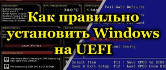
How to disable Secure Boot
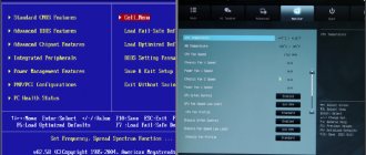
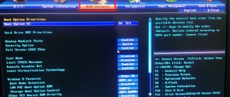
The Secure Boot option in UEFI prevents the launch of unauthorized OS and software components when the device boots by scanning the digital signatures of the boot loaders, thereby ensuring security. In some cases, it may interfere with booting the device from a flash drive when installing Windows 7, XP or Ubuntu, and therefore requires disabling. Deactivation may also be required before enabling BIOS emulation, since the settings may not initially display the option to switch the mode.
Depending on the firmware version, Secure Boot may be located in Boot, Security, Advanced – System Configuration, Authentication. To deactivate the secure startup option, move it to the Disable position. In some firmware variations, in addition to activating the BIOS and disabling Secure Boot, in the software settings you also need to specify the type of OS being loaded - “Other OS”.
UEFI Boot Manager operation algorithm
The UEFI boot concept is significantly different from the BIOS boot concept. If you remember the BIOS, the bootstrap code int 19h (bootstrap loader) was responsible for loading there, the task of which was only to load the master boot record (MBR) from the boot device into memory and transfer control to it. In UEFI, everything is somewhat more interesting; it contains its own full-fledged built-in bootloader, which is called UEFI Boot Manager (UEFI Boot Manager or simply Boot Manager), which has much richer functionality.
UEFI Boot Manager is a standard generic UEFI module.
Boot Manager implements a fairly wide range of functions, which include loading UEFI images such as: UEFI first-stage OS loaders, UEFI drivers, UEFI applications. Booting can be done from any UEFI image located on any UEFI-supported file system located on any physical storage medium supported by the platform. UEFI Boot Manager has its own configuration, the parameters of which are located in the form of a number of variables in a common NVRAM (Non-volatile RAM).
EFI NVRAM is a shared memory area designed to store UEFI configuration parameters, available for use by firmware developers, hardware manufacturers, operating system developers, and users.
UEFI parameters are stored in NVRAM as variables, which are classically represented by a parameter name = value pair. These variables contain a large number of parameters that relate to different functional parts of the UEFI, that is, in addition to the UEFI Boot Manager parameters, NVRAM stores many other UEFI parameters. However, for the purposes of this chapter, we are only interested in variables related to the UEFI Boot Manager. This is primarily the global variable BootOrder, which points to boot handle variables named Boot####. Each Boot#### element is a pointer to a physical device and (optionally) can even describe a file that is a UEFI image that should boot from this physical device.
All boot devices are described as a full path, that is, they contain a readable name of the boot file, so they can be added to the boot menu.
This is roughly how I imagine the algorithm for enumerating media during UEFI operation:
As we can see, UEFI Boot Manager parses BootOrder, that is, it loads the device path of each Boot#### element in the order specified by the value of the BootOrder variable and tries to boot from the specified device. If there is an error, the boot manager moves on to the next element. In addition, a so-called download list is generated. This list is relevant for the UEFI settings interface and looks like the familiar standard boot menu. The UEFI Boot List is generated based on the BootOrder variable and is used to allow the user to make changes to the order and configuration of boot devices. How is the BootOrder itself formed? And it’s very simple, for example, during the installation of the Windows operating system, the installer creates an ESP partition (if it does not exist) on the installation disk, formats this partition into the FAT file system, then places its boot loader (for Windows 7+ this is the file bootmgfw.efi) and some other files along the path \EFI\Microsoft\Boot\. Once the OS installation is complete, the Windows installer creates a variable in the EFI NVRAM called Boot#### (where #### is a hexadecimal number) that references the Windows boot manager named bootmgfw.efi.
Multiboot in UEFI
From the very beginning of the mass distribution of personal computers, from time to time the task arose of deploying several operating systems on one PC, which could host one or more physical media. Not so long ago, the situation was significantly changed by the discovery of virtualization technology, but this did not completely eliminate the problem. In its classical sense, in relation to stations that boot using the traditional PC/AT BIOS method using the classic MBR markup, multiboot was a third-party code in the main boot sector (MBR), which loads the so-called boot manager (multibooter), which stores settings for each operating system installed on the computer and providing a menu for selecting how to boot a particular OS. If we talk about our time, that is, about multibooting in relation to media partitioned using GPT markup, then a lot has changed now. As we have already noted, UEFI can directly work with GPT disks, so the task of installing multiple operating systems is greatly simplified. Now all the functions of the multibooter are taken over by the built-in UEFI Boot Manager, the operating principles of which we described above. The OS installer only needs to do what it already does very well: place the bootloader on a special ESP partition in “its” directory hierarchy, after which this bootloader becomes “visible” in the UEFI settings. In addition to the OS installer, now the user himself, using the settings (graphical/text interface UEFI), can manually add a bootloader located on any physical media connected and visible to the system. All these bootloaders added in various ways become available through the Boot Menu, which the user can configure/call directly while UEFI is running, that is, at the initial stage of booting the PC. In other words, multibooting in UEFI is simply a matter of running UEFI applications (OS-specific bootloaders) located on mounted media on a special ESP partition in a directory hierarchy rooted at /EFI.
Formatting a flash drive
Next you need to format the media. To do this, you need to enter the clean command. After this, you need to create a primary partition on the disk. This can be done using the create partition primary command. After this, the created partition should be made active. To do this, enter the active command. After this, you can display a list of sections. To do this, enter list volume in the command line. We find the section that we created. If it is listed as number 3, then enter the command select volume 3. After this, you need to format it in the FAT32 system. To do this, enter the command format fs=fat32. The basic bootable media is thus ready. But that is not all. You need to assign a drive letter to the flash drive. This can be done using the assign command. After that, enter exit and exit the command line.