Good day, Geektimes!
Has everyone already heard about USB Type-C? The one that's two-way, fast-fashionable, charges your new MacBook, makes your hair silky smooth, and promises to be the new standard for connectivity for the next ten years?
So, firstly, this is a connector type, not a new standard. The standard is called USB 3.1. Secondly, we need to talk specifically about the new USB standard, and Type-C is just a nice bonus. To understand what the difference is, what is behind USB 3.1 and what is behind Type C, how to charge an entire laptop using a USB cable, and what else can be done with the new USB Type-C:
Briefly about the main thing
USB as a standard appeared almost twenty years ago.
The first specifications for USB 1.0 appeared in 1994 and solved three key problems: unification of the connector through which equipment that expanded the functions of a PC was connected, simplicity for the user, and high speed data transfer to and from the device. Despite certain advantages of the USB connection over PS/2, COM and LPT ports, its popularity did not come immediately. USB experienced explosive growth at the beginning of the 2000s: first cameras, scanners and printers were connected to it, then flash drives.
In 2001, the first commercial implementations of the USB that is familiar and understandable to us appeared: version 2.0. We have been using it for the 14th year now and it is designed relatively simply.
Alternate Modes
If up to this point we were talking exclusively about proprietary developments, now it’s time to look at related technologies. Type C will also allow you to connect to monitors with DisplayPort, MHL and HDMI. You can’t ignore Thunderbolt 3, which guarantees data and video transfer at high speeds. Through this interface you can daisy chain connect up to 6 peripheral devices (for example, monitors). It's really hard to imagine a situation where this is really necessary.
USB 2.0
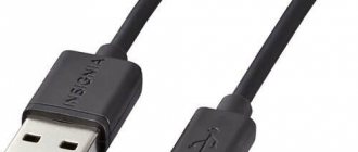
Any USB cable version 2.0 and lower has 4 copper conductors inside. Two of them transmit power, the other two transmit data. USB cables (according to the standard) are strictly oriented: one end must connect to the host (that is, the system that will manage the connection) and it is called Type-A
, the other to the device, it is called
Type-B
. Of course, sometimes in devices (such as flash drives) there is no cable at all; the “to-host” connector is located directly on the board.
On the host side there is a special chip: a USB controller (in desktop computers it can be either part of the system logic or placed as an external chip). It is he who initializes the operation of the bus, determines the connection speed, the order and schedule of data packets, but these are all details. We are most interested in connectors and connectors of the classic USB format.
The most popular connector that everyone used was USB Type-A of the classic size: it is located on flash drives, USB modems, at the ends of the wires of mice and keyboards. Full-size USB Type-B is a little less common: printers and scanners are usually connected with this cable. The mini version of USB Type-B is still often used in card readers, digital cameras, and USB hubs. Through the efforts of European standardizers, the micro version of Type-B has become de facto the most popular connector in the world: all current mobile phones, smartphones and tablets (except for the products of one fruit company) are produced with the USB Type-B Micro connector.
Well, probably no one has really seen USB Type-A micro and mini formats. Personally, off the top of my head I can’t name a single device with such connectors. Even the photographs had to be taken from Wikipedia:
Hidden text
Type-A mini:
Type-A micro:
All these connectors have one simple thing in common: inside there are four contact pads that provide the connected device with both power and communication:
| Contact number | 4 | 3 | 2 | 1 |
| Designation | GND | D+ | D- | VBUS |
| Wire color | Black | Green | White | Red |
With USB 2.0 everything is more or less clear. The problem with the standard was that two conductors were not enough to transmit data, and the specifications developed in the middle of the first decade did not provide for the transmission of large currents through power circuits. External hard drives suffered the most from such limitations.
USB 3.0
To improve the characteristics of the standard, a new USB 3.0 specification was developed, which contained the following key differences:
- Five additional contacts, four of which provide additional communication lines;
- Increase in maximum throughput from 480 Mbit/s to 5 Gbit/s;
- Increasing the maximum current from 500 mA to 900 mA.
In addition, 4 more connectors have appeared that are electrically and mechanically compatible with USB Type-A version 2.0. They allowed both USB 2.0 devices to be connected to 3.0 hosts, and 3.0 devices to 2.0 hosts or via a 2.0 cable, but with limitations in power supply and data transfer speed.
USB 3.1
Since the fall of 2013, specifications for the updated USB 3.1 standard have been adopted, which brought us a Type-C
, transmission of up to 100 W of power and doubling the data transfer speed compared to USB 3.0. However, it is worth noting that all three innovations are just parts of one new standard, which can be applied all together (and then the device or cable will receive USB 3.1 certification) or separately. For example, technically, inside a Type-C cable, you can organize at least USB 2.0 on four wires and two pairs of contacts. By the way, Nokia pulled off such a “feint”: its Nokia N1 tablet has a USB Type-C connector, but inside it uses regular USB 2.0: with all the limitations on power supply and data transfer speed.
From words to practice
Connector selection
Before choosing a connector, you need to decide which interface transmission you need to support in your design. At the moment, the main ones in embedded development are USB2/USB3 interfaces, so we will consider them further.
It is important to understand that the USB connector is one of the most frequently used and most subject to wear and tear parts of your device, so it is necessary that it is made well and can withstand a large number of connections.
Most manufacturers offer a wide range of different connectors. Let's consider the main parameters that are worth paying attention to.
Important! If the device is not a one-off and subsequent serial production is intended, you should pay attention to a parameter such as Part Status . If it has the status Active , then this connector is active and will be supported by the manufacturer in the near future. If the component has a different status, there is a possibility that you will not be able to buy such a connector again in the future.
Number of contacts
Depending on the supported interfaces, the connector may have fewer pins. So, if support for high-frequency interfaces operating on RX/TX lines (USB3.2/USB4/TBT3/DP) is not required, then you can select connectors with 16 pins or less:
- 24 contact – all interfaces are supported;
- 16/14 contacts – only interfaces that do not use high-speed differential pairs (TX1± TX2± RX1± RX2±) are supported, for example USB 2.0, PD and others. Example: CX90M-16P from Hirose Connector.
Connector installation method
There are different ways to install the connector. They all differ in parameters; we will consider only the main ones.
- Type of connector installation on a printed circuit board:
- Surface Mount - the connector is installed on the surface of the printed circuit board. Example: CX90B1-24P from Hirose Connector;
Board Cutout - a space is cut out on the printed circuit board for the connector. Example: CX90M-16P from Hirose Connector.
Examples in pictures
Surface Mount / surface mount
Board Cutout / cutout in a printed circuit board
- Connector orientation relative to PCB:
- Right Angle - standard type of connector installation at a right angle to the printed circuit board. Example: CX90B1-24P from Hirose Connector;
- Vertical Right Angle - the connector is installed at a right angle, but in a vertical position. Example: KUSBX-SL-CS1N14-B from Kycon.
Vertical - the connector is installed perpendicular to the printed circuit board. Example: CX80B1-24P from Hirose Connector;
Examples in pictures
Right Angle / right angle
Vertical / vertical
Vertical Right Angle / vertical at right angle
- Type of contact installation on a printed circuit board:
- Surface Mount - All connector pins are installed via surface mounting. Example: 12401544E4#2A from Amphenol;
- Surface-lead mounting - some contacts are installed using surface mounting, the rest are installed using through-out mounting. Due to the output contacts, this type of connector is easier to accurately position during manual installation. Example: 632723300011 from Wurth Elektronik.
Lead-out mounting - all contacts are installed using lead-out mounting. There are quite a few such connectors; they all have 16/14 contacts, that is, they are suitable for supporting only the USB2.0 interface. Example: KUSBX-SL-CS1N14-B from Kycon;
Examples in pictures
Surface mounting of contacts
Lead mounting of contacts
Surface Mounting
Important! When choosing a connector, you should pay attention to the length of the pins, since some manufacturers offer several options for the same connector for printed circuit boards of different thicknesses.
Connector type
Many connectors look very different from each other, as they are designed to work in different conditions. Many of the connectors produced have various degrees of protection (Ingress Protection), IP65, IPX2 and so on. Due to these requirements, the external design of the connector is quite specific, so it is difficult to use it in standard thin-walled housings. Therefore, if there is no need, we recommend using standard connectors without any degree of protection.
Examples in pictures
IPX7 connector
Standard connector
Implementation into the project
In this article, we consider only UFP (Upstream Facing Port) Sink, that is, USB devices that cannot be identified when connected as a host device or power source. More detailed information on UFP and the development of DFP (Downstream Facing Port) and Source devices (power supply) can be found in the specifications linked above.
Let's consider two connection options:
- only with support for USB2.0 interface;
- with support for USB2/3.2 interfaces.
USB2.0 interface support
You need to do the following:
- Connect resistors (Rd resistor) with a pull-up value to ground to pins A5/B5 (CC1/CC2) 5.1 kΩ ± 20%, as shown in the figure below. When a device is connected to a cable, a pair of resistors Rp–Rd forms a voltage divider. By measuring the received voltage, the host determines which CC pin is connected to the host, thereby determining the orientation of the cable. Due to the fact that only USB 2.0 is used, the orientation does not matter, so a resistor Rd is connected to each of the CC pins. If resistor Rd is connected to only one of the pins, and the other is left “in the air,” then the device will only work with a certain cable orientation. Resistors Ra are installed inside the cable and have a different nominal value from Rd.
- Connect pins A6–B6 (D+) and A7–B7 (D-). This step is necessary for successful operation of the device with any cable orientation.
- Also, most Type-C connectors have pins connected to the connector body (Shield). It is also recommended to connect them to ground through a protection circuit. The protection circuit must be placed as close to the connector as possible. Depending on the purpose and characteristics of the devices, the protection scheme may differ. An example of a protection scheme is presented below under the spoiler.
- RX1/TX1, RX2/TX2, SBU1/SBU2 are not used and do not need to be connected.
Diagram for USB2.0 interface
Printed circuit board:
- To support USB 2.0, a double-sided PCB is sufficient.
- Line parameters for USB 2.0: differential impedance – 90 Ohm ± 10%;
- maximum length difference within paired lines is 1.1 mm;
- The maximum track length on the board is 200 mm.
An example of a Type-C connector trace for a USB2.0 interface
An example of a Type-C connector trace for a USB2.0 interface (connector: 2129691-1 from TE Connectivity)
USB2.0/USB3.2 Gen 1 / Gen 2 interface support
You need to do the following:
- Connect pins A6–B6(D+) and A7–B7(D-).
With pins CC1/CC2 in this example everything is a little more complicated. If our device supported the USB 3.2 Gen 2×2 interface, then it would be enough to pull the CC1/CC2 pins to ground through resistors Rd with a nominal value of 5.1 kOhm. In any cable orientation, all high-frequency differential pairs would be connected to each other.
Since in our case only two high-frequency differential pairs (RX/TX) are used instead of four, the following problem arises: data can be transmitted either on the first pair or on the second, depending on the orientation of the connection.
- To solve this problem, you can use a combination of two microcircuits:
- orientation detection chips connected to the CC pins. It is necessary to determine the orientation of the connected cable. Example: TUSB320 from TI and PTN5150A from NXP;
2 in 1 multiplexer for USB 3. After the chip determines the connection orientation, it directly or through the microcontroller sets the multiplexer to a mode in which the differential lines of the device are connected to the active differential lines of the cable. Example: CBTU02043 from NXP.
Diagram for USB3.2 Gen2x2 interface
Diagram for USB3.2 Gen1/Gen2 interface
Printed circuit board:
- For high-frequency differential pairs, we recommend using a minimum of a six-layer PCB, and the support layers must be completely dedicated to GND. Otherwise, when transitioning lines between the upper and lower layers, it will be necessary to use capacitors (stitching capacitor) to connect the supporting layers instead of simple vias. To reduce stubs, it is recommended to connect tracks to the connector with output contacts from the bottom layer (if the connector is installed on the top layer).
- Line parameters for USB3.2 Gen 1: differential impedance – 90 Ohm ± 10%;
- maximum length difference within paired lines is 0.15 mm;
- maximum track length on the board is 200 mm;
- AC coupling capacitors – 100nF (case 0402 recommended).
Example of tracing a Type-C connector for USB2.0/3.2 interfaces
Four-layer printed circuit board using capacitors connecting the supporting layers (connector: 2305018-2 from TE Connectivity)
Six-layer printed circuit board (C1, C2,R1 - shield), (632723300011 from Wurth Elektronik)
USB 3.1, Type-C and power
USB PD
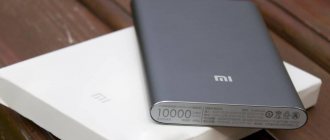
standard is responsible for the ability to transfer truly serious power . According to the specifications, to be certified as USB PD, the device and cable must be able to transmit current with a power of up to 100 Watts, both in both directions (both to and from the host). In this case, the transmission of electricity should not interfere with the transmission of data.
There are currently only two laptops that fully support USB Power Delivery: the new MacBook and the Chromebook Pixel.
Well, then, who knows, maybe we’ll install sockets like this at home?
USB Type-C and backward compatibility
USB as a standard is strong in its backward compatibility.
Find an ancient 16 megabyte flash drive that only supports USB 1.1, insert it into a 3.0 port and go. Connect a modern HDD to a USB 2.0 connector, and if it has enough power, everything will start, the speed will just be limited. And if that’s not enough, there are special adapters: they use the power circuit of another USB port. The speed will not increase, but the HDD will work. It’s the same story with USB 3.1 and the Type-C connector, with only one amendment: the new connector is geometrically in no way compatible with the old ones. However, manufacturers have actively begun producing both Type-A <=> Type-C wires, as well as all kinds of adapters, adapters and splitters.
USB-C, what is it?
In simple words, this is a connector for connecting various external devices to a computer, phone or other gadgets. First, a double-sided USB cable or wire is connected to this connector, which connects, for example, a computer with other external devices (Screen 1).
In another way, the connector on this wire is called HDMI. Here is information from Yandex (screen 2).
And the USB Type-C connector is an improved version of USB-C, to which you can connect not one peripheral device, but several at once. For example, a computer monitor, a second computer, a phone, a tablet and other devices. Type-C is often found in “adapters”. (Screen 3).
The new type of Type-C connector is not yet available on all computers. Manufacturers of mobile phones, computers and laptops are introducing it into production.
What's on USB Type-C now?
Since the technology is young, there are very few devices with USB 3.1.
There are slightly more devices with a USB Type-C cable/connector, but still not enough for Type-C to become as common and natural as Micro-B, which any smartphone user has. On Type-C personal computers, you can expect it already in 2016, but some manufacturers have taken and updated the line of existing motherboards. For example, USB Type-C with full USB 3.1 support is available on the MSI Z97A Gaming 6 motherboard.
ASUS is not far behind: ASUS X99-A and ASUS Z97-A motherboards support USB 3.1, but, unfortunately, do not have Type-C connectors. In addition, special expansion cards have been announced for those who do not want to either upgrade the motherboard or give up a pair of USB 3.1 ports.
SanDisk recently introduced a 32 GB flash drive with two connectors: classic USB Type-A and USB Type-C:
Of course, don’t forget about the recent MacBook with passive cooling and only one USB Type-C connector. We’ll talk about its performance and other delights sometime separately, but about the connector today. Apple abandoned both its “magic” MagSafe charging and other connectors on the case, leaving one port for power, connecting peripherals and external displays. Of course, if one connector is not enough for you, you can buy an official adapter-splitter to HDMI, a classic USB and a power connector (the same Type-C) for... $80. We can only hope that Type-C will come to Apple mobile devices (and this will be the end of the zoo with wires for smartphones), although the chances of such an update are minimal: was it in vain that Lightning was developed and patented?
One of the peripheral manufacturers, LaCie, has already released a stylish external drive with support for USB 3.1 Type-C for the new MacBook. Its price, however, is absolutely Apple, but what can you do - you have to pay for new technologies and the PORSCHE DESIGN inscription.
In addition to Apple, Google is also flirting with USB 3.1 Type-C: the new ChromeBook Pixel, in addition to interesting characteristics, also received a corresponding port.
And, of course, don’t forget about the device from Nokia. Their N1 tablet was one of the first to receive a Type-C connector, although without support for USB 3.1 functions.
Flaws
From a technical point of view, USB Type-C is almost perfect. So why hasn't it become the most popular yet? Why are manufacturers not in a hurry to equip their equipment with it? There are no obstacles to technical equipment, but there are significant reasons that slow down this process.
First of all, it has a unique physical structure, so to connect most gadgets you need adapter cables, all kinds of splitters and adapters. If the connected device does not support USB 3.1, such a connection simply becomes meaningless, since the maximum data transfer speed and power support will not be provided.
Most of the released computer, mobile, audio and video equipment is equipped with Type-A, Type-B Mini/Micro, which do not support USB 3.1 or even 3.0. The mass transition to USB Type-C will reduce demand for existing products that do not have it. Regardless of the desires and hopes of users, manufacturers deliberately push back effective technology and slow down its spread.
Secondly, even if two connected devices have Type-C, it may not be possible to get all the benefits. This is due to imperfect technology for processing and transmitting information from certain categories of devices. For example, you can synchronize a smartphone and a personal computer/laptop via Type-C. However, data transfer in both directions will be limited, since the hard drive will not be able to provide maximum speed.
Yes, new technology is available, it is being used, but a complete transition is still far away. You need to understand that in the event of a complete transition to USB Type-C, all outdated equipment will have to be sent for recycling.
Ratings: 18 , average: 4.78
Results
USB 3.1 will finally become the “king” of connectors.
You can use it to connect almost anything: an external drive, a display, peripherals, a power adapter, and even an array of SSD drives. Bandwidth and 100 W of transmitted power are a serious claim to success. Imagine the world in 5 years? No matter where you go, there is a charger, and the connector fits, and you don’t need to ask. It’s easy to connect a camera, a telephone, and in general everything, everything, everything... And only in the accounting department they used floppy disks and will continue to use them.
Our previous reviews: » Two months with LG G Watch R » The evolution of Razer mice using the example of DeathAdder and Naga » Studying Philips' TV flagship: Part 1 | Part 2
Thank you for your attention!