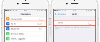
Transmitting an Internet signal using a wireless connection is the most popular way to gain access today. For this purpose, special types of devices are used, called a router or router. They may have different qualities and characteristics, for example, Wifi communication standards, connection speed and others.
One of the most important parameters is the operating mode of the device. In the router interfaces, you can select Wi-Fi protocols and standards to get optimal speed and throughput, as well as wireless network security. To determine the most successful parameter in the settings, you need to understand what Wifi protocols are and what impact the presented settings have.
Transmitter Power (Tx Power, Output Power)
Different units of measurement . Some manufacturers indicate power in mW, some in dBm. You can convert dBm to mW and vice versa, without bothering yourself with conversion formulas, using our calculator.
It is worth noting that the relationship between these two power representations is non-linear. This is easy to see when comparing the ready-made values in the correspondence table, which is located on the same page as the above calculator:
- An increase in power by 3 dBm 2-fold increase in mW .
- An increase in power by 10 dBm 10-fold increase in mW .
- An increase in power by 20 dBm gives a 100-fold .
That is, by decreasing or increasing the power in the settings by “only” 3 dBm, we actually decrease or increase it by 2 times.
The bigger, the better? Theoretically, there is a direct relationship - the more power, the better, the farther the signal “hits”, the greater the throughput (the amount of data transmitted). For point-to-point backbones with directional antennas raised in open spaces, this works. However, in many other cases, things are not so straightforward.
- Interference in the city . Cranking up the power to maximum can do more harm than good in urban environments. Too strong a signal, reflected from numerous obstacles, creates a lot of interference, and ultimately negates all the benefits of high power.
- Air pollution. An unreasonably strong signal “clogs” the transmission channel and creates interference for other participants in the WiFi traffic.
- Synchronization with low-power devices. Reducing TX Power may be necessary when connecting to low-power devices. For good connection quality, especially two-way traffic, such as interactive applications, online games, etc., you need to achieve symmetry in speed for incoming and outgoing data. If the difference in signal strength between the transmitting and receiving devices is significant, this will not have the best effect on the connection.
There should be exactly as much power as needed. Even when setting up access points, it is recommended to first reduce the power to a minimum and gradually increase it, achieving the best signal quality. At the same time, remember the non-linear relationship between power expressed in dBm and actual energy power, which we talked about at the beginning of the article.
It is also important to consider that range and speed depend not only on power, but also on the antenna gain (gain), receiver sensitivity, etc.
Which Wi-Fi mode to choose
Typically, any device such as a router or modem is set to a mixed mode of use (802.11n/ac mixed or 802.11b/g/n mixed). This is needed to solve problems with connecting devices and increase the chances of compatibility between two devices. This allows you to connect to the router not only from new smartphones, but also from an old laptop.
There is a claim that installing 802.11n (“Only n”) can significantly increase data transfer speeds. This doesn't always work, but you can try. If a person does not have old gadgets that do not support 802.11n, then you can safely install this mode and check the quality of the wireless network and take measurements.
Popular 802.11 bgn set for work
Some routers only operate on the 5 GHz frequency band. It is recommended to set the mixed type “n/ac” for them. You can always check the benefits and changes in speed. It is enough to set a certain mode and take measurements. Then another mode is set. And so on until the optimal one is found. It is important not to forget which settings were changed so that you don’t have to look for them later and reset the router.
Thus, there are many Wi-Fi modes, as well as standards. To choose the protocol to use, you need to determine whether all devices in the house support it. You can read more about the technical part of Wi-Fi on Wiki.
Receiver sensitivity (Sensitivity, Rx Power)
WiFi receiver sensitivity is the minimum level of incoming signal that the device can receive. This value determines how weak signals the receiver can decipher (demodulate).
Accordingly, you can select equipment for the conditions in which you want to increase your wireless connection.
“Weak” in this case does not necessarily mean “not powerful enough.” A weak signal can be as a result of natural attenuation during long-distance transmission (the farther from the source, the weaker the signal level), absorption by obstacles, or as a result of a poor (low) signal-to-noise ratio. The latter is important, since a high noise level drowns out and distorts the main signal, to the point that the receiving device cannot “select” it from the general stream and decrypt it.
Sensitivity (RX Power) is the second important factor affecting communication range and transmission speed. The greater the absolute value of the sensitivity, the better (for example, a sensitivity of -60 dBm is worse than -90 dBm).
Why is sensitivity displayed with a minus sign? Sensitivity is determined similarly to power in dBm, but with a minus sign. The reason for this is the definition of dBm as a unit of measurement. This is a relative value and the starting point is 1 mW. 0 dBm = 1 mW. Moreover, the ratios and scale of these quantities are arranged in a unique way: with an increase in power in mW several times, the power in dBm increases by several units (similar to power).
- The power of radio transmitters is greater than 1 mW, therefore it is expressed in positive values.
- The sensitivity of radio transmitters, or more precisely, the level of the incoming signal, is always much less than 1 mW, so it is customary to express it in negative values.
It is simply inconvenient to present sensitivity in mW, since it will contain numbers such as 0.00000005 mW, for example. And when expressing sensitivity in dBm, we see more understandable -73 dBm, -60dBm.
Sensitivity is an ambiguous parameter in the characteristics of access points, routers, etc. (however, like power, in fact). In reality, it depends on the signal transmission speed and in the equipment characteristics it is usually indicated not by one number, but by an entire table:
The screenshot from the Nanobeam M5-300 specification lists the various WiFi signal transmission parameters (MCS0, MCS1, etc.) and what signal strength and sensitivity the device shows with them.
Here we run into another question - what do all these abbreviations mean (MCS0, MCS1, 64-QAM, etc.) in the specifications, and how can we still use them to determine the sensitivity of a point?
What is MCS (Modulation and Coding Scheme)?
MCS in English stands for “modulation and coding schemes”. In common parlance it is sometimes simply called "modulation", although this is not entirely true for MCS.
What is modulation? To coordinate spatial flows between different devices and increase transmission efficiency, signal modulation has been used in radio engineering for quite some time. Modulation is when a signal with information is superimposed on the carrier frequency, modified in a certain way (encryption, changing amplitude, phase, etc.).
The result is a modulated signal. Over time, new and more efficient modulation methods are being invented.
But the MCS index, which is established by IEEE standards, means not just signal modulation, but a set of parameters for its transmission:
- modulation type,
- information encoding speed,
- number of spatial streams (antennas) used during transmission,
- transmission channel width,
- duration of the protective interval.
The result is a certain channel speed obtained when transmitting a signal, taking into account each of these sets.
In this table you can see what speed (as well as power, sensitivity and other parameters) corresponds to what M CS , according to the approved 802.11n and 802.11ac standards.
For example, if we choose from the above specification the best combination of power (26 dBm) and sensitivity (-96 dBm) is MCS0.
Let's look at the correspondence table and see what kind of transmission parameters MCS0 has. Frankly speaking, sad parameters:
- 1 antenna (1 spatial stream)
- Transfer speeds from 6.5 Mbit/s on a 20 MHz channel to 15 Mbit/s on a 40 MHz channel.
That is, the point provides the above signal power and sensitivity only at such low speeds.
When determining the sensitivity of Wi-Fi access points (and power), it is better for us to focus on the MCS indices in the specification (datasheet) with more efficient, standard transmission parameters.
For example, in the same specification for Nanobeam, let’s take MCS15: power 23 dBm, sensitivity -75 dBm. In the table, this index corresponds to 2 spatial streams (2 antennas) and a speed from 130 Mbit/s on a 20 MHz channel to 300 Mbit/s on 40 MHz.
Actually, it is precisely these parameters (2 antennas, 20 MHz, 130/144.4 Mbit/s) that Nanobeam works in most cases (MCS15 in the Max Tx Rate field in AirOS is usually set by default).
Thus, the standard, that is, most often used, sensitivity of the Nanobeam M5-300: -75 dBm.
However, it should be taken into account that sometimes what is needed is not high speed, but link stability or range; in these cases, in the settings you can change the modulation to MCS0 and other low channel speeds.
The MCS index table (or speed table, as it is sometimes called) is also used for reverse search: they calculate what speed can be achieved at a certain power and sensitivity of Wi-Fi equipment.
Story
In the heyday of Wifi, data transfer speeds were quite low. A radio channel was used, the speed of which did not exceed one Megabit per second, sometimes reaching two. The first high-frequency format for wireless communication was called IEEE 802.11a. It reached speeds of up to 54 Megabits per second, which was considered very fast. The operating frequency corresponded to five Gigahertz.
In 1999, a new type of Wifi was released, which did not become the expected continuation, but received new technology. Its name is IEEE 802.11b. HR-DSSS technology is used and the use of an unlicensed frequency range of 2.4 GHz is provided. The transmission speed was up to eleven Megabits per second.
Important! All WiFi specifications, standard encryption parameters and other characteristics are tested for compatibility and certified by a special organization called the Wi-Fi Alliance.
For a long period, 802.11b was the most widespread and popular type, on the basis of which many networks based on wireless technology were built. Now, it has been replaced by g, which is also gradually giving way to the Wifi n standard, the speed of which is quite high.
802.11g was released back in 2002 and is a 2.4 Gigahertz frequency with a Wifi data transfer rate of 54 Megabits per second. Wifi speed from a to b, g, n, constantly increased. With the release of new drivers it also increased.
The latest versions are backwards compatible with 802.11b. For example, 802.11g backwards compatibility can be done using the DSSS modulation technique. Then the connection speed will be limited to 11 Mbit/s, or in the OFDM modulation technique, in which the speed will be at the level of 54 Megabits per second. It turns out that such a standard is the most optimal for connections of the type under consideration.
Bandwidth (Channel Sizes)
WiFi uses the division of the entire frequency into channels to transmit data. This allows you to streamline the distribution of radio frequency air between different devices - each equipment can choose a less noisy channel for operation.
In simple terms, this division can be compared to a highway. Imagine what would happen if the entire road was one continuous strip (even one-way) with a stream of cars. But 3-4 lanes already bring a certain order to traffic.
Add and divide. The standard channel width in WiFi is 20 MHz. Starting with 802.11n, the possibility of combining channels was proposed and regulated. We take 2 channels at 20 MHz and get 1 at 40 MHz. For what? To increase speed and throughput. Wider bandwidth means more data can be transmitted.
Disadvantage of wide channels: more interference and shorter data transmission distance.
There is also a reverse modification of channels by manufacturers: reducing their width: 5, 10 MHz. Narrow channels provide greater transmission range, but lower speed.
The modified channel width (reduced or increased) is the bandwidth .
What it affects: the throughput and “range” of the signal, the presence of several bands - the ability to fine-tune these characteristics.
What is Wi-Fi standard
Wi-Fi is a wireless communication standard that appeared in 1998, but began to develop back in 1985, when the United States decided to open several wireless network bands. At that time, it was used to operate microwave ovens and other appliances.
Corporate logo
Practice shows that many people do not even know what standards are, a Wi-Fi wireless network, and so on. For many, it’s all one thing – the Internet. This is a little wrong. “Wi-Fi” is not a global network, but a trademark. If a person buys equipment (router, access point, modem, etc.) with a Wi-Fi sticker, then he receives a certified product that will function and exchange data with other similar wireless devices.
The term itself was introduced by a special Alliance that developed it. It was originally called IEEE 802.11b-compatible, but this name was quickly abandoned due to its length. It was decided to shorten it and modify it. "Wi-Fi" doesn't mean anything. It was simply in tune with Hi-Fi and this is a plus when advertising the standard. Later it began to stand for Wireless Fidelity.
Logo of the company that developed the standard
Most likely, such misconceptions of people are associated with incorrect advertising of technologies. During its existence, there were several major campaigns, but people remembered the product not by its qualities, but by the characteristics of the devices and networks associated with it.
Important! A striking example is the Xerox company. People are so accustomed to its copiers and printers that now everyone calls any such machine a “copier” and a copy a “photocopy.”
Antenna Gain (Gain)
This is another important parameter that affects signal range and throughput.
Gaining a WiFi antenna does not mean that it will add strength to your signal. An antenna is a passive device that does not consume electricity and cannot “add power” at least according to the law of conservation of energy.
Gain is a relative value measured in isotropic decibels (dBi). The starting point for calculating this coefficient (the same numbers that we see in the “Antenna Gain” column in the technical specifications) is a virtual (non-existent) reference isotropic antenna.
How can an antenna amplify the signal?
Let's take for example a flashlight with the ability to change the focus of the beam.
A wide beam will illuminate a large area, but not close.
A narrow beam will illuminate a smaller area, but will “reach” further.
Antenna gain works in much the same way.
Let's look at an example of a radiation pattern.
Directional pattern (DP) is a graphical display of the propagation of WiFi signal power from the source. The antenna gain value is plotted along the radius of the diagram. Since the beam propagates in space both horizontally and vertically, the radiation patterns are made in two planes: horizontal and vertical.
Pattern of the reference (non-existent) isotropic antenna:
As you can see, here the radiation goes in all directions, both in the horizontal and vertical planes. In 3D it looks something like this:
In real antennas - directional, sectoral and even omnidirectional - the antenna redistributes the signal and “focuses” it .
Diagram of an omnidirectional antenna.
The figure shows the Omni antenna pattern (the antenna is double polarized, so “slices” of the horizontal and vertical planes of both polarizations are presented).
In the vertical plane (Elevation), the omnidirectional antenna pattern has “shrinked” and narrowed. The redistributed energy was used to amplify the signal in the horizontal plane; the antenna “added” power in one direction, “taking” it from the other .
This is why omnidirectional antennas often have the lowest gain, and directional antennas have the highest gain (more potential for signal redistribution).
Of course, the antenna gain is uneven over the entire coverage area. If the parameters of a directional antenna indicate, for example, 20 dBi, then this gain applies only to the main lobe of the antenna, not to the side lobes. There are formulas for calculating the gain, and, accordingly, the power at any point in the radiation pattern, but we will not dwell on them here.
So how much power did the antenna gain increase? Despite the fact that the power and gain of the antenna are expressed in seemingly different quantities (dBm and dBi), in fact both are decibels, they are simply counted from different reference points. Decibels can be easily added and subtracted from each other; in fact, that’s their beauty.
Therefore, knowing the transmitter power (in dBm) and the antenna gain (in dBi), you can calculate what the power became after amplification (using the main lobe of the radiation pattern). We add power (for example 23 dBm) and gain (for example 30 dBi) and we get 53 dBm .
Converting dBm to mW, we see that the power has increased from 200 mW (23 dBm) to almost 200 W!
NetStress
A more accurate program for measuring wireless transmission speed on a local network.
- Download the program here.
- Install on two laptops;
- When you launch the program, you will need to select a connection - in this case we select wireless.
- The program itself will try to connect to the second laptop. If there are more than 2 network devices, a window will pop up where you will need to select a second laptop. Next, simply start the test with the “Start” button.
- Now on the right side you will see the transfer speed in KBps (Kilobits per second). To convert it to megabits, you just need to divide the number by 1024. For example, your number shows 50,000. This means the speed will be 50,000 / 1024 = "" 48 Mbit per second.
iperf console program
Iperf is an excellent router connection speed test program. There is more hassle with it, but it also shows the speed with the smallest error, so I would use it. I will try to write as detailed as possible.
- And so, we have two laptops and both are connected via Wi-Fi to our router. Therefore, we perform further actions for both laptops.
- Download the utility - https://iperf.fr/iperf-download.php#windows.
NOTE! By the way, you can also check the connection speed of your phone, since the program is cross-platform and there are even versions for Android and iOS systems. For PC there are versions of Windows 7, 8, 10 and Linux.
- There will be an archive with one “.dll” and “.exe” file. Place both of these files on drive “C” at the root without any extra folders.
- Launch the Windows command line (cmd.exe).
- We write:
- Now we are at the root of the disk, where we have the program.
- On one of the laptops that will act as a server, we write: